Meter Circuits
This article covers the measurement of voltage, current, resistance, and
power. This article assumes a basic familiarity with voltage and current
dividers.
The D'Arsonval Movement
The d'Arsonval movement is the heart of most analog meters. It consists of a
movable coil that is placed within the field of a permenant magnet. When current
goes through the coil, it creates torque which turns the coil. A pointer is
attached to the coil, and a small restoring spring is added which pushes the
pointer back over to the side when no current is applied.
The important thing to remember about d'Arsonval movements is that the
deflection of the pointer is directly proportional to the current going through
the coil.
Basic Meter Circuits
The Ammeter
 A d'Arsonval
movement measures current. However, it does not always measure in the range that
we want it to measure. How do we make a general purpose ammeter out of a
d'Arsonval movement? The answer is to use a simple voltage divider. By placing a
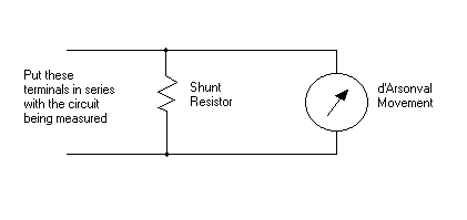
shunt resistor across the terminals of a d'Arsonval movement, we create a curent
divider. The value of resistance that we chose then determines the meter's full
scale range.
d'Arsonval movements are usually specified by the full scale current value,
and the corresponding voltage across the coil when this full scale current is
reached. The resistance of the coil may be specified instead of the voltage, and
Ohm's Law easily lets us determine the missing values.
Suppose, for example, that our particular d'Arsonval movement reads full
scale at 1 mA, and that the voltage across the coil at 1 mA is 50 mV. Using
Ohm's Law, we can easily determine that the coil has a resistance of 50 ohms
(from V=IR).
Next, let's assume that we want to make an ammeter with a full scale reading
of 10 mA. This means that at full scale, 1 mA is going through the movement
(remember from the above paragraph that this particular meter reads full scale
at 1 mA), which leaves us 9 mA that has to be going through the shunt resistor.
At full scale, the meter drops 50 mV. In a current divider, both resistors have
the same voltage across them, so our shunt resistor also has to have 50 mV
across it. Now we know the voltage and current through our shunt resistor, and
we can use Ohm's Law again. Plug in I and V and solve for R. You should get 5.55
ohms (approximately).
To use an ammeter, we place it in series with the device being measured. This
means that all of the current flowing through the device also must flow through
the ammeter. If the device draws too much current, then the meter could be
damaged. This is why it is very important for ammeter circuits to be properly
fused.
Ideally, we like to assume that the ammeter has a negligable effect on the
circuit. In the real world, the ammeter does have some resistance and does
effect the circuit. Our example meter above has 5 ohms of resistance (5.55 ohms
in parallel with 50 ohms for the meter movement). If you are trying to measure
the current through a 1 ohm resistor, the meter has 5 times the resistance of
the resistor you want to measure! This could very easily cause the circuit to
function improperly.
The Voltmeter
 A voltmeter can be constructed by
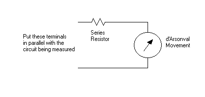
placing a resistor in series with a d'Arsonval movement. This makes a simple
voltage divider. If we continue using our example d'Arsonval movement from
above, let's now assume that we want to make a voltmeter with a full scale
reading of 150 volts. We know that the current through the resistor is 1 mA,
since the full scale current of the movement is 1 mA, and any current going
through the movement must also be going through the series resistor (where else
would it go?). We know the current through our resistor (1 mA) and the voltage
across it (150-0.050). Using Ohm's Law, this gives us a resistance of 149,950
ohms.
Voltmeters are connected in parallel with the device being measured. The
resistance of the device being measured should be taken into consideration,
since the meter's resistance may have a noticable effect on how the circuit
operates.
The Ohmmeter
 An ohmmeter can be constructed
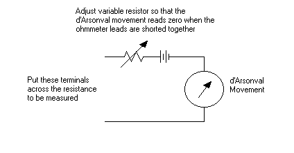
out of a d'Arsonval movement with a series resistor, similar to the above
voltmeter, with a battery also in series. The series resistor is chosen so that
the meter movement deflects to full scale when the terminals of the meter are
shorted together. A variable resistor is often used, so that variations in the
battery may be accounted for.
This creates a meter with a scale that is not linear. Lower resistances will
have a dominant effect on the current. For higher resistances, the resistance of
the meter is more dominant. Therefore, the resistance scale is wider on the low
end and narrower on the high end.
The Wheatstone Bridge
 A more accurate circuit that can
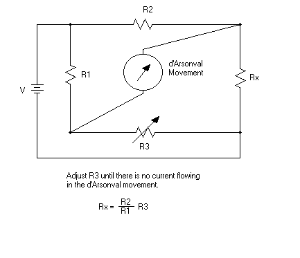
be used to measure resistance is called a Wheatstone Bridge. The variable
resistor, R3, is adjusted until there is no current flowing through the meter
movement. At this point, we know that Rx (the resistance being measured) is
equal to (R2/R1)R3. This circuit can cover a much wider range of resistances if
R1 and/or R2 can be varied. In practical Wheatstone Bridges, R3 may consist of
several resistors which can be switched into the circuit using decimal type
dials (one dial for the thousands, another for the hundreds, another for the
tens, etc). A very accurate meter with a very large range (up to about 1,000,000
ohms) may be constructed in this manner.
The Wattmeter
Digital Meters
Digital meters do not use d'Arsonval movements, but they still work on the
same basic principles. A very precise analog to digital converter and some sort
of display (usually a LCD) is used in place of the d'Arsonval movement.
Calibration
How do you know that a volt is really a volt? How do you know that your
meter's resistors are accurate? In the U.S., we have the NIST (National
Institute of Standards and Technology) which creates standard voltage sources,
etc. that can be used to calibrate a meter. Very high quality meters will have a
calibration certificate that is tracable back to NIST standards. This
calibration is usually only guaranteed for a certain period of time (such as one
year).
Most hobbyists do not need this level of accuracy for home use, and do not
need to worry about calibration to NIST standards.
 A voltmeter can be constructed by
placing a resistor in series with a d'Arsonval movement. This makes a simple
voltage divider. If we continue using our example d'Arsonval movement from
above, let's now assume that we want to make a voltmeter with a full scale
reading of 150 volts. We know that the current through the resistor is 1 mA,
since the full scale current of the movement is 1 mA, and any current going
through the movement must also be going through the series resistor (where else
would it go?). We know the current through our resistor (1 mA) and the voltage
across it (150-0.050). Using Ohm's Law, this gives us a resistance of 149,950
ohms.
 A d'Arsonval
movement measures current. However, it does not always measure in the range that
we want it to measure. How do we make a general purpose ammeter out of a
d'Arsonval movement? The answer is to use a simple voltage divider. By placing a
shunt resistor across the terminals of a d'Arsonval movement, we create a curent
divider. The value of resistance that we chose then determines the meter's full
scale range.
 An ohmmeter can be constructed
out of a d'Arsonval movement with a series resistor, similar to the above
voltmeter, with a battery also in series. The series resistor is chosen so that
the meter movement deflects to full scale when the terminals of the meter are
shorted together. A variable resistor is often used, so that variations in the
battery may be accounted for.
 A more accurate circuit that can
be used to measure resistance is called a Wheatstone Bridge. The variable
resistor, R3, is adjusted until there is no current flowing through the meter
movement. At this point, we know that Rx (the resistance being measured) is
equal to (R2/R1)R3. This circuit can cover a much wider range of resistances if
R1 and/or R2 can be varied. In practical Wheatstone Bridges, R3 may consist of
several resistors which can be switched into the circuit using decimal type
dials (one dial for the thousands, another for the hundreds, another for the
tens, etc). A very accurate meter with a very large range (up to about 1,000,000
ohms) may be constructed in this manner.