Engineering an Energy Efficient,
Adaptable Hybrid Bicycle Motor System
(EEEAHBMS)
By
Scott
Denenberg
Submitted
to:
The Weller Foundation Inc.
The Barton L. Weller Scholarship
2002-2003
April 8, 2003
Engineering an Energy Efficient,
Adaptable Hybrid Bicycle Motor System
(EEEAHBMS)
By
Scott
Denenberg
Submitted
to:
The Weller Foundation Inc.
The Barton L. Weller Scholarship
2002-2003
April 8, 2003
Table of
Contents
0. Preface
1. Project Description
1.1 Combining Human and Electric Power
1.2
Energy Efficient Regenerative Braking
1.3 Adaptability
1.4 Safety
2. Goals for Learning
2.1 The Engineering Process
2.2
Power Electronics
2.3
CAD (Computer Assisted Drawing) design
2.4
Software design
2.5 Interactive C
2.6
Advanced Circuitry
2.7 Testing and Debugging
3. Brainstorming Designs
3.1 Drive System
3.1.1 System Design
3.1.2 Motors
3.1.3 Batteries
3.1.4 Drive Wheels
3.2 Control System
3.3 Regenerative Breaking System
3.4 Mounting System
3.5
Safety System
4. Collecting Hardware
4.1 Motor
4.2 Batteries
4.3 Sheave and Bushing
4.4 Channel
4.5 H-Bridge Controller
4.6 5K Potentiometer
4.7 HandyBoard (HB)
4.8 Battery Charger
4.9 Bicycle Tire and Tube
4.10 Miscellaneous
5. Construction
5.1 Saddlebag
5.2 T-hinge and Aluminum Angle Stock
5.3 Motor and Batteries
5.4 Mounting of Saddlebag
5.5 Rear Control Box
5.6 Front Control Box
5.7 Trimming the Channel
5.8 Rear Reflector
6. Electronics
6.1 Batteries, Controller and Motor Circuit
6.1.1 Rear Control Box Electronics
6.1.2
Front Control Box Electronics
6.2 Current Sensor Circuit
6.3 Odometer Sensor Circuit
6.4 Printed Circuit Board in Rear Electronics Box
7. Software Design and Implementation
7.1 Learning Interactive C
7.2 System Requirements
7.3 Software Requirements Document
7.4 Implementing Software
8. Testing, Debugging and Results
8.1 Initial Testing of Motor, Controller, and
Batteries
8.2 Testing of the Current Sensor
8.3 Testing of the Odometer
8.4 Software Debugging
8.5 Final Testing and Results
9. Support
9.1 Jeffrey Denenberg
9.2 Steven Buroff
9.3 Motors and Drives
9.4 The Trumbull Business Education Initiative
9.5 Larry Farrell
9.6 The Bass Family and The Gottlieb Family
9.7 Danielle Lenois
10. Next Steps
10.1 Complete Software
10.2 Stabilize Physical Structure
10.3 Battery Tray
10.4 Lower Resistance Current Sensor
10.5 Further Testing of EEEAHBMS
10.6 Belt Friction Drive
10.7 Lighten Entire Structure
Appendices
A. Costs of EEEAHBMS
B. Electronics Connections
C. Software Requirements Document
D. EEEAHBMS Software
0. Preface
This report documents the Engineering an Energy-Efficient, Adaptable Hybrid Bicycle Motor System project from conception to completion. The report follows a structure that mimics the engineering process which guided the project, beginning with a general project description and goals for learning (Sections 1 and 2). The report documents the design process (Section 3), describes the process through which the hardware was purchased (Section 4), details how the physical structure of the motor system was built (Section 5), explains the electronics and circuitry of the bicycle (Section 6), and documents the software component of the project (Section 7). Finally, the report concludes with the testing, debugging, and results of the project (Section 8), a record of all of the support given towards completing this project (Section 9) and future intentions for the project (Section 10).
Special thanks are due to Jeffrey Denenberg, Steven Buroff, the Trumbull Business Education Initiative, and Motors and Drives, for large donations of time and materials.
1. Project Description
The idea for Engineering an Energy-Efficient, Adaptable Hybrid Bicycle Motor System (EEEAHBMS) stems from the recent burst in popularity of hybrid cars that utilize the combination of a combustion engine and battery power for optimum efficiency. The goal of this project is to create a similar union between human power and electric power, turning a bike into an efficient and practical machine for long distance travel.
1.1 Combining Human and Electric Power
A bicycle is often an unreasonable form of long distance travel because pedaling is exhausting, especially when pedaling uphill. A hybrid system overcomes this difficulty. The rider will select a desired speed at which he wishes to travel. The bicycle will have an onboard computer making constant comparisons between the current speed at which the bicycle is traveling and the inputted target speed of the rider. Based on this data, the computer will execute one of two general scenarios:
1. When peddling or traveling faster than the desired speed, the motor will act as a generator and send the extra energy provided by the rider into the battery for later use, slowing the bicycle down more efficiently than brakes (see section 1.2 Energy Efficient Regenerative Braking).
2. When traveling at less than the desired speed, the motor will provide the extra power required to achieve the desired speed.
The result will be a machine that effectively combines the power of man and electricity and makes it practical to use the bicycle for longer distances.
1.2 Energy
Efficient Regenerative Braking
The largest inefficiency in riding a bicycle is in the braking system. The essence of
braking is the removal of the kinetic energy of motion from the bicycle. When hand brakes are utilized, brake pads clamp down on the wheel, slowing down its rotation. This means that the kinetic energy is being removed through friction. While this is effective, the energy lost due to friction will never be returned to the bicycle. It has been dissipated in the form of heat and sound.
This project aims to overcome this inefficiency. Rather than braking through friction when
the bicycle is traveling faster than the target speed, the regenerative braking
system will take the extra kinetic energy and channel it back into a battery
for future use by the motor.
1.3 Adaptability
The aim of EEEAHBMS is not to simply transform one bicycle into a hybrid between human power and electric power. Its aim is to create an efficient motor system that is universal for almost every bicycle. This universality revolves around the mounting arrangement. With very few adjustments, the EEEAHBMS mounting arrangement will be compatible with almost every bicycle, making it relatively simple to transfer from bicycle to bicycle. This project does not include the bicycle itself; EEEAHBMS is an independent system that can be removed and added to an arbitrary bicycle without affecting its functionality.
1.4 Safety
Safety is an important consideration for all newly designed systems. EEEAHBMS needs to be proven to be safe for use through many repetitive and deliberate tests, as well as incorporating many safety functions to address unexpected malfunctions during operation.
The EEEAHBMS is no exception. In addition to redundant testing throughout the course of construction, it will have multiple safety features just in case something goes wrong during use. Such safety precautions include:
·
an on-off switch
·
an emergency software and hardware shutdown switch
·
a current overload shutdown procedure
·
a routine that does not allow the motor to start until
the bicycle is traveling at a minimum speed of 3mph.
2. Learning Goals
Engineering an Energy-Efficient, Adaptable Hybrid Bicycle Motor System is a research and development engineering project that is heavily focused on research. While it is the development phase that creates the final product, the research and subsequent knowledge gained is prerequisite for the development.
2.1 The Engineering Process
As stated above, EEEAHBMS is an engineering project: an idea is being developed, designed, implemented and tested. Therefore, while there are many different components to this project, every single one of them is a branch of the engineering process. At the end, each of these different sections of the project represents research, learning and development along the way to the final product. Hence, the experience gained during the multi-step process will be relevant in real world engineering projects.
2.2 Power Electronics
The design of this
hybrid motor system hinges on an in-depth knowledge of power electronics. The entire project revolves around
understanding energy efficiency, energy exchange and energy storage. The main task of power electronics is
to control and convert electrical power from one form to another. The
topic of power electronics includes:
With efficiency a
large goal in this project, it is necessary that the relative energy
efficiencies of different motors, batteries and controllers are understood
before a selection and purchase of materials is made.
2.3
CAD Design
The construction of the physical structure and mounting
system of the motor system requires multiple custom-made metal components. Before a machinist can create these custom
made parts, an accurate and to-scale drawing needs to be created. The Computer Aided Design (CAD) software
CADKey ’97 R2 will be used. However, no
CAD program is intuitive and self-explanatory.
They all require some expertise in order to create a 3-D drawing that
makes physical sense. In order to gain
some fluency in the program, the included guided tutorials will be
followed. However, this in itself is
not sufficient. In addition, self
instruction through experimentation will be the main method of learning exactly
how CADKEY ‘97 R2 works.
2.4
Software Design
Software design is not a straightforward process. Approaching it with a rough outline and basic idea of what needs to be accomplished, much like an essay, is a mistake. Without an exact statement of how to implement the goals of the project, the software cannot be written. This is because each section of the software does not build on the last. Instead, the different portions of the program work together simultaneously. Therefore, just writing code from the beginning to the end like writing a book is not the correct approach.
With the guidance of a professional programmer, the correct procedure for software design will be learned and then followed. This includes listing the purposes and functions of the project, and then creating a detailed Software Requirements document before even beginning to program. During this portion of the project, the structure of the procedure-oriented programming language, Interactive C, will be learned in preparation for the program implementation.
2.5 Interactive C
One of the largest components of EEEAHBMS is its
software. Since the 68HC11 “Handy Board” Computer will be used as
the onboard computer to control the hardware, its programming language,
Interactive C, will also be used.
Interactive C is a subset of the C programming language, and mastery of
its use will be absolutely necessary if the software portion of this project is
to be completed.
Learning a
programming language is not a simple task.
In order to become familiar with the syntax of this programming
environment, some guidance will be necessary.
However, beyond this, self-guided experimentation and the creation of
test programs will provide the experience needed before diving into this large
programming project. The EEEAHBMS
programming in itself will be a learning process as mistakes will be
continually discovered during the frequent testing and debugging.
2.6
Advanced Circuitry
The electricity and
magnetism portion of a Physics C course provided the foundation for the
electrical knowledge needed to complete the circuitry component of
EEEAHBMS. However, the project requires
knowledge that goes beyond the scope of that course.
Additional knowledge
is required in the areas of:
·
Digital Logic
and Boolean Algebra
·
Operational
Amplifiers
·
Voltage
Dividers
·
Capacitors
Digital Logic and
Boolean Algebra are necessary to understand the 7493 4-bit binary counters
which will be implemented in the speed sensor circuit.
An operational
amplifier amplifies a voltage according to the ratio of resistors surrounding
it and will be used to amplify the small signal from the current sensor. Also necessary for the current sensor is a
voltage divider, which is essentially the exact opposite of an operational
amplifier. It creates a point in the
circuit where the voltage is reduced to a fraction of the original.
Finally, while
capacitors were covered in Physics C, their use for this project was not
covered. In EEEAHBMS, a capacitor will be used as a
filter for a pulse-width modulated square wave. The purpose of this filter will be to make the average value of
the current from the H-bridge readable.
All of these topics
will be discussed in more detail later in the report.
2.7
Testing and Debugging
The last, and often
most difficult part of the engineering process, is testing and debugging. Unfortunately, one of the rules of
engineering is that nothing works perfectly the first time. There is always some unexpected occurrence
that needs to be solved after the fact.
The goal of the testing portion of the process is to pinpoint the error;
debugging is the process of repairing the mistake.
In order to be a
successful tester and debugger, a technique needs to be developed. It’s not always as straightforward as a
problem and a solution. Often,
innovation and clever manipulation of the resources at hand are necessary. There is a direct relationship between the
complexity of a project and the amount of troubleshooting that needs to be
done. Due to the complexity of
EEEAHBMS, there is bound to be more than enough testing and debugging to be
done. This experience will provide an
accurate representation of working in the real world of engineering.
3. Brainstorming Designs
The first few weeks
of work on EEEAHBMS were spent researching the feasibility and functionality of
different physical designs. Each
possible design was evaluated for its strengths and weaknesses, and then a
final design was chosen. While no
construction was accomplished during this period, the necessary material list
was created and a general design was finalized. Without a brainstorming period, no project can be successful.
3.1
Drive System
Motorizing a bicycle
is not an original idea. While there
have been no efforts to create a human power - electrical power hybrid as
EEEAHBMS aims to accomplish, many different drive systems for motorized
bicycles exist. Therefore, looking
towards other system designs was a logical place to start.
3.1.1 System Design
The simplest,
cheapest and most widely used drive system is a friction drive. A
friction drive consists of a motor turning a wheel which turns the wheel of a
bicycle through friction. While it can
be effective if correctly implemented, it does have a number of drawbacks. All of the drawbacks seem to revolve around
“slippage”. Since the only method of
connection between the motor’s drive wheel and the bicycle wheel is friction,
the entire system is liable to slip.
And, with slippage, there is a loss of energy and efficiency, as well as
the potential for wearing down and ruining the wheel. In order to overcome slippage, the original wheel of a bicycle is
often scrapped, especially if it is a mountain bicycle. Mountain bikes have especially bumpy treads,
and this bumpiness limits the surface area between the drive wheel and the
bicycle wheel. Therefore, a rough
bicycle wheel, a compromise between a slippery smooth wheel and the mountain
bike wheel, is ideal. However, there is
yet another problem. If the wheel gets
wet, there is an increased danger of slipping.
While this is only a difficulty if it is raining, it needs to be taken
into consideration.
The next drive
system is actually a number of variations belt pulley which involves a motor driving a belt which drives
a pulley on the shaft of a bicycle. The
different variations include different types of belts:
1. Friction belts
2. Chains
3. Toothed belts
The tooth belt is
the compromise between the friction belt and the chain. Motorcycles are the classic example of a
“motorized bicycle” that use this model of a belt pulley. However, this design has its own drawbacks
as well. This design does not lend
itself well to the EEEAHBMS because it is not adaptable. The pulley stem that needs to be mounted to
the wheel complicates the mounting arrangement and relies too heavily on the
structure of the hub of the bicycle wheel.
In addition, the belt pulley is dangerous. An exposed drive belt is a threat to the rider, because if a
shoelace or a piece of clothing gets caught, it will be drawn into the
motor. This makes it necessary to build
a shield around the belt system, creating even more complications and making
the system bulkier and heavier.
A third drive system
is the hub design. This design consists of a motor built into
the hub of the bicycle. While it is the
ideal drive system it terms of power and mounting economy, it has many draw
backs that far outweigh its advantages:
1. A hub motor is extremely expensive, and in order to get enough power
to accomplish the goals of EEEAHBMS, the budget would be exhausted on the motor
alone.
2. A hub motor is also extremely specialized, and the electronics
required are beyond the scope of this project.
The reasons for this will be discussed later.
3. Because the hub motor would be built into the hub of the bicycle, it
makes adaptability difficult.
4. A hub motor does not do regenerative braking. Instead of acting like a generator when it
needs to slow down, the hub motor free-wheels, or coasts to a stop.
For these reasons,
the hub drive design did not lend itself well to EEEAHBMS.
The final drive
system design is an original one devised while researching all of the different
possible drive systems. Its design is a
variation on the belt pulley drive. It
has been named the belt friction drive. It consists of a motor driving a belt which
is attached to a free wheeling pulley on the other side of the wheel. This belt is pressed down onto the wheel and
it drives the wheel through friction.
It has many advantages over the other drive systems. While the belt friction drive is similar to
the friction drive system because it moves the wheel through friction, it does
so over a much larger surface area than the friction drive wheel would. Therefore, slippage is much less of a
problem. Belt friction drives are also
portable from bike to bike because the belt friction drive does not involve
mounting directly onto the wheel of the bicycle.
After analyzing the
different options for the drive system, the top choice was the original design
of the belt friction drive. Beyond
being one of the simplest, most effective, and containing the least drawbacks,
it also added originality to the bicycle design that can be patented in the
future.
However, when
choosing a design, the top choice is not always the right choice. When attempting to make a concrete drawing
of what the design would look like, it became obvious that the belt friction
drive was overly complicated for a first attempt. Since any overly complicated design is bound to fail, the
friction drive was chosen. The
drawbacks of the friction drive system are easily overcome, and it is by far
the easiest to implement. In addition,
the friction drive is the first step towards the belt friction drive. Once the friction drive is functioning, with
the addition of a belt and a free wheeling pulley, it can be adapted into a
belt friction drive. Therefore, the design choice was to build a friction drive
system with the intentions of adapting it to a belt friction drive system in
the future.
Based on this system
design, it is possible to move onto more specific questions regarding the drive
system:
1.
What type of
motor will drive the bike?
2.
What type of
battery will supply the power to the motor?
3.
What type of
wheel will be used as a drive wheel?
To decide on a type
of motor, battery and drive wheel, the same process of enumerating all of the
different possibilities and then listing their strengths and weaknesses was
followed.
3.1.2 Motors
The first class of
motors was the very low cost motor. Every motor has a field and coils that move
with respect to each other. In general, the coils rotate on an armature through
the field, using brushes to continually flip the current in the coils. The flipping of currents allows the coils to
have the correct magnetic polarity to be attracted and repelled by the field at
the appropriate times, keeping the motor running rotating. There are exceptions to that rule
however. In some motors, it is the
field that rotates and the coils that remain stationary. In these low cost motors, the field is
created by a separate field winding.
While this creates a very light motor, the very low cost motors are not
terribly efficient. Much energy is wasted
in the current that flows through the field windings. While controlling the field current provides a very easy way to
control the speed of the motor, it also poses a problem. The current in the motor and the speed of
the motor are an inverse relationship.
The lower the current, the faster the motor rotates and vice versa. However, if the current in the field
windings reaches zero, or even approaches zero, the motor will spin too quickly
and destroy itself.
Another class of
motors is the brushless motor. An example of a brushless motor is a hub
motor. They are extremely efficient,
very powerful, and lightweight.
However, they require very complicated electronics because, instead of a
brush, electronics inside of the motor flip the currents of the field windings
and the rotating coils to keep the motor turning. While this is an extremely effective approach, it would be
necessary to purchase all of the motor control electronics which would
shortchange the learning goal of EEEAHBMS. Therefore, the brushless motors were
not chosen.
The last motor class
is the permanent magnet motor. These motors sport a permanent magnet that
sets up a constant field as opposed to the field windings with the variable
field in the low-cost motors. While
this permanent magnet does cause the motor to be a little heavier, it also is
much more efficient. Also, the constant
field sets up a steady state speed. The
voltage put across the motor determines the speed that it will rotate at,
regardless of the load. Therefore, with
this type of motor, the speed would be independent of whether the bicycle was
going uphill or downhill. And, to make
things even simpler, the voltage has a direct linear relationship with the
speed of the motor. This makes the
electronics connected to the motor very simple. (See 3.2 Control System for more details on the electronics of
the bicycle.)
The information that
served as the first indicator of the linear relationship between voltage and
speed came from the following graph (found at
store.evparts.com/shopping/products/mt5113/Torque%20Curves.htm):
Figure 3a: LEM-130 Torque Curves
This graph shows
that the rotations per minute at the equilibrium speed (speed that the motor
accelerates to and then stabilizes) of a permanent magnet motor is independent
of the load placed on the motor. This
was intriguing, and, after further research, the fact that a permanent magnet
motor has a steady state speed was discovered (see 3.2 Control System for more
details).
Based on this
information, the motor class choice for EEEAHBMS was the permanent magnet
motor.
3.1.3 Batteries
The choices for
rechargeable batteries were:
1.
Nickel cadmium
and nickel metal-hydride
2.
Wet cell lead
acid
3.
Sealed lead
acid
Before the different
classes of batteries could be examined, a few calculations were required. By examining other motorized bicycle
designs, it was determined that to accomplish the goals of EEEAHBMS, a
half-horsepower motor was needed.
Taking into account some inefficiency, a half-horsepower is equal to
about 400 Watts, which is a measure of power.
And Power is equal to Voltage X Current. From some quick research on different gauge wire and the relative
currents they could handle, a 24 Volt battery (a convenient multiple of the
standard 12 Volt car battery) was chosen because that left the current that
needed to be handled at 20 Amps. And, a
reasonable 10 or 12 gauge wire can easily handle 20 Amps. Finally, the rating in amp-hours of the
battery was going to be determined by cost and weight, with a target amp-hour
rating of about 12. An amp-hour is a
measure of how much current a battery can supply before draining itself. (One amp supplied for one hour is an
amp-hour. And, 100 amps supplied for
1/100 of an hour is also an amp-hour.)
From research on the success of other motorized bicycles, it seems that
12 amp-hours would give the bicycle a range of 10 miles. Obviously, a higher rating in amp-hours is
desirable, but as the rating of a battery rises, so do its cost and its
weight.
The first class of
rechargeable batteries that was examined included nickel cadmium batteries and nickel metal hydride batteries. Both of these types are deep discharge and can be charged many
times before losing effectiveness. In
addition they have one of the best energy storage to weight and volume
ratios. They are such good batteries
that they are even used in hybrid cars.
However, nickel cadmium and nickel metal hydride batteries have some
serious flaws. Nickel cadmium batteries
have “memory.” These batteries, if not
fully discharged before charging, “remember” the degree to which they were last
discharged. Then, during the next power
cycles, this memory will prevent the battery from ever discharging below the
point to which it was discharged last, despite the fact that the battery is
capable of being further discharged.
Since EEEAHBMS will not always fully discharge a battery before charging
it back up, this characteristic is highly undesirable. While the nickel metal hydride batteries do
not have the same memory characteristic, both the nickel cadmium and nickel
metal hydride batteries are extremely expensive. For example, a 6 Volt nickel metal hydride cell, rated at 1.2
amp-hours costs $20. If you connect 4
of these batteries in series, the desired 24 Volt rating is achieved. And if you connect 10 of these 4 battery
strings in parallel, a reasonable rating of 12 amp hours is achieved. Therefore, 40 batteries are required to
produce 12 amp-hours at 24 Volts. This
would cost $800, which is far above the budget for this project.
The second class of
batteries is the wet-cell lead acid
battery. These are the batteries that
are typically used in cars. While these
batteries store a lot of energy and are incredibly reliable, they do not like a
deep discharge. For example, on the
fourth or fifth time a car battery is drained completely from the headlights
being left on, it needs to be replaced.
Another drawback of the wet-cell lead acid batteries is that they need
to be maintained vertical at all times.
If tipped, these batteries are dangerous because of the acid they
contain. While a vertical orientation
can be insured inside a car under normal circumstances, a bicycle is much more
likely to be accidentally tipped.
The third class of
battery is the sealed lead acid battery. This battery is very similar to a wet-cell
lead acid battery; however its acid is captured in a gel or in a sponge-like
membrane. Therefore, tipping is no
longer an issue. In addition, the
sealed lead acid batteries can be discharged and charged over 500 times without
any harm to the battery, as long as a special battery charger is used and care
is taken not to overcharge or discharge the battery. And, finally, these batteries are not expensive. Two 12 V batteries, both rated at 12 amp-hours
cost less than $90, one tenth of what a nickel metal hydride battery would
cost.
Based on this
analysis, the battery choice for EEEAHBMS was the sealed lead acid battery.
3.1.4 Drive Wheels
The drive wheel is
the wheel that the motor drives, which in turn drives the bicycle wheel. This decision was fairly easy, as there were
only two possibilities with one having clear advantages.
The first
possibility was a grinding wheel. While this would provide a lot of friction
to the wheel, it had a serious flaw. If
the grinding wheel were to slip for any reason, it would do what it is made to
do: grind. And before long, the wheel
would be destroyed.
The other drive
wheel possibility was a sheave (pronounced
“shĩv”). A sheave is very similar to a pulley, with
the only difference being that a pulley is free wheeling and a sheave locks on
to a shaft. While a sheave does not
have as much friction as a grinding wheel, it is much more suited for
EEEAHBMS’s purposes. It is not as large
of a threat to grinding the wheel down, it has features which make it easy to
connect to the motor, and it is compatible with the intentions to test a belt
friction drive in the future.
Based on this
analysis, the drive wheel class choice for EEEAHBMS was the sheave.
3.2
Control System
Once all of the
components of the drive system were selected, all of the other components
quickly fell into place. Based on the
selection of a permanent magnet motor, the control system needed to be able to
produce a variable voltage in order to control the speed of the motor. As previously explained, there is a linear
relationship between the voltage placed across the motor, and the speed of the
motor. And, this is independent from
the load placed on the motor. This is
true because as the motor speeds up, it produces a back EMF. This back EMF is basically an anti-voltage,
which is linearly related to the speed of the motor. When the back EMF equals the variable voltage supplied by the
controller, the motor stops accelerating.
For a permanent
magnet motor, the standard variable voltage supply is an H-bridge. An H-bridge is comprised of two sets of two
switches, making the shape of an H.
These sets of switches, when turned on and off, alternately switch the
battery positively and negatively across the motor. These switches flip back and forth approximately 1000 times per
second, and set up an average voltage across the motor. The average voltage depends on the duty
cycle, which is determined by an inputted voltage (from the Handy Board
computer). For example, if the switches connect the battery across the motor
equally positively and negatively, then the average voltage will be 0 as they
will cancel. However, if the duty cycle
connects the battery across the motor for 75% of the time positively, and 25%
of the time negatively, then the average voltage is 50% of the positive nominal
voltage, which in the case of EEEAHBMS, is 12 volts.
3.3
Regenerative Braking System
The design of the
regenerative braking system for EEEAHBMS is very simple; it only required
choosing an H-bridge that did regenerative braking. The decision on whether to make the H-bridge or to buy it was an
easy one. An H-bridge is a complicated
piece of equipment, and to build it from scratch would be unpractical when they
are reasonably priced. H-bridges rated
at 20 amps continuous duty are priced from $100-$150, depending on features.
H-bridges have three
major features:
1. Bidirectionality
2. Dynamic Braking
3. Regenerative Braking
A bidirectional H-bridge is capable of
running a motor forwards and backwards.
While this adds minimally to the cost of the H-bridge, it was
undesirable for EEEAHBMS. A bicycle is
not meant to run backwards, and if a bidirectional H-bridge was used, the
bicycle could start moving backwards accidentally and potentially hurt the
rider or the bicycle. For example, if
the H-bridge’s duty cycle connected the battery across the motor positively
only 25% of the time, the motor would run backwards at half speed. This is the opposite scenario from when the
battery was connected across the battery 75% of the time.
Another feature that
an H-bridge can have is dynamic
braking. Dynamic braking is the
capability for the H-bridge to short out the motor and shunt all of the current
to ground. This causes the motor to
stop immediately. Dynamic braking adds
to the price of an H-bridge because it takes extra transistors for the H-bridge
to be able to handle the current involved in shorting out the motor. The dynamic braking feature wasn’t required
for the EEEAHBMS because it stops the motor too quickly. Dynamic braking would cause damage to the
wheel and loss of control of the bicycle.
However, having an H-bridge that did include dynamic braking was not as
undesirable as a bidirectional H-bridge.
This is because it is difficult to accidentally enable the dynamic
braking feature. It requires an extra
connection and extra wiring that can easily be omitted.
Regenerative
braking is the H-bridge feature
that is most pertinent to this section of the design. The regenerative braking function requires that the H-bridge can
handle the flow of current in both directions: from the battery to the motor
and from the motor to the battery. And,
because transistors usually only like to conduct current in one direction, the
addition of transistors for the regenerative braking function does increase the
H-bridge’s price.
3.4
Mounting System
Once the basic
design of EEEAHBMS was created, the next step was to figure out how to mount it
on a bicycle. However, this wasn’t as
simple as figuring out how to mount EEEAHBMS on the bicycle in the garage. In order to achieve the adaptability goal of
the project, the mounting arrangement needs to be simple and compatible with
all bicycle frames.
After an informative
trip to Cycle Fitness in Monroe, and
a long discussion with the manager of the bicycle shop, a basic mounting
arrangement was designed. There are two
aspects of a bike that are universal: the bicycle seat and the rear axel. Therefore, these two locations are the
logical place to mount the motor. In
fact, these are also the two easiest places for mounting. The seat post of the bicycle seat provides
an easy, sturdy place for clamping, and the rear axel has threaded mounting
holes. Every bicycle has these standard
threaded holes for mounting rear fenders or carriers for babies and school
books.
While this mounting
arrangement is simple and compatible to most bicycle frames, there are a few
exceptions. The first exception is the
racing bike. Racing bicycles have very
thin frames, designed to be light and aerodynamic. They cannot safely support
the addition of a 60 pound motor system.
Therefore, EEEAHBMS will not be compatible with racing bicycles. However, this is not a terrible loss, as it
is difficult to imagine a bicycle racer wishing for electric assistance.
The other exception
is any bicycle that has a set of shock absorbers on the rear wheel. Rear shocks cause the rear axel to move
relative to the bicycle seat. And, this
is not compatible with a mounting arrangement that clamps onto these two parts
of the bicycle.
One last mounting
detail needed to be addressed. Since a
friction drive is going to be used, the bicycle cannot have a mountain bike tire. Mountain bike tires are very bumpy and have
a lot of knobby irregularities which are meant to increase traction and
stability off-road. However, these
bumps would prevent the drive wheel from having contact with a consistently
smooth and regular wheel surface.
Therefore, for mountain bikes, the rear tire would have to be replaced
in order to be compatible with a friction drive.
Once the mounting
arrangement was decided, the manner by which the weight of the motor and
battery of EEEAHBMS were to be distributed needed to be determined. Maintaining a balance on the bicycle wasn’t
going to be easy with a 23 pound motor and two 9 pound batteries. However, there is a logical solution. The two 9 pound batteries can balance the 23
pound motor if they are placed on the opposite side of the bicycle. So, a “saddle-bag” design for mounting was
adopted. A metal channel is mounted to
the seat post of the bicycle and supported by an angle-iron mounted to the rear
axel. Across this channel are
saddlebags with a compartment on each side of the bicycle: one side for the
motor and the other side for the two batteries. With this general design decided, the feasibility of the weight
distribution of the motor and batteries was proven.
3.5
Safety System
The final system to
be defined was the safety system.
Safety is always of foremost importance in design.
When researching
other motorized bicycles, a common safety precaution emerged: the motor would
not start unless the bicycle was already going 2-3 miles per hour. This is to prevent the bicycle from running
off on its own, without the rider on it, or before the rider is in control of
the bicycle. It’s a logical precaution
and was incorporated into the design of EEEAHBMS.
Another safety
measure that was incorporated was a computer shut down if the current spikes
above a specified “high water mark.”
The electronics of the bicycle isn’t rated to handle currents above 20
amps continuously, and, therefore, it needs to be protected from damage caused
by the motor pulling too high of a current.
With the computer monitoring the current, it is a simple safety measure
to have the software shut everything down if the current spikes above the high
water mark.
In designing a
safety system, redundancy is the key.
Therefore, in addition to the software shutdown if the current exceeds
the high water mark, there will be a hardware shutdown as well. This will be accomplished with a simple
fuse. If the current gets too high, the
fuse will blow; the metal inside the fuse will melt, breaking a circuit.
Another aspect of
the safety system concerned braking.
Regenerative braking is not appropriate for sudden, emergency
stops. Dynamic braking was first
considered for this purpose. It seemed
to be the easiest way to ensure a rapid stop.
However, during testing, this was proven to be highly unsafe because it
stopped the motor too quickly. A sudden
stop could damage the motor and the wheel, as well as causing the rider to lose
control.
Therefore, a more
elegant and less brute force solution to the requirement for a sudden stop was
designed. The handbrake serves as an
emergency switch. Pumping it causes the
computer to reset the bicycle’s desired speed to zero, which slows the bicycle
down quickly. And, with the bicycle’s desired
speed at zero, the handbrakes can then be used in tandem as they would normally
be used, achieving a quick and safe stop.
As another safety
precaution, there is be a main software shutdown switch as well as a hardware
shutdown switch. And, finally, there is
a main on-off switch. Once again,
redundancy is the key. However, the
main on-off switch cannot be flipped while the motor is in use because it is
not rated at high currents.
4. Collecting Hardware
Once the overall
general design for EEEAHBMS was completed, the next step was to purchase all of
the major components of the project.
For details on the prices of each component, see Appendix A Costs of
EEEAHBMS.
4.1
Motor
Based on the
EEEAHBMS design, the motor requirement was a ½ horsepower permanent magnet
motor, rated at 24 V and 20 amps continuous duty. So, the motor search began.
After shopping around on multiple websites, it was determined that
motors are extremely expensive. While
surplus motors are available on e-bay for between $150-$200, it was impossible
to find a motor with the correct specifications. This left a price range of $300-$400, which was unacceptable for
the EEEAHBMS budget.
After contacting Motors and Drives, a family owned
company, the motor search began to look more promising. Casey O’Donnell, an engineering student at
Fairfield University and member of the Motors
and Drives team helped to find the best motor suited for EEEAHBMS. And, after pinpointing the desired motor,
Casey donated it.
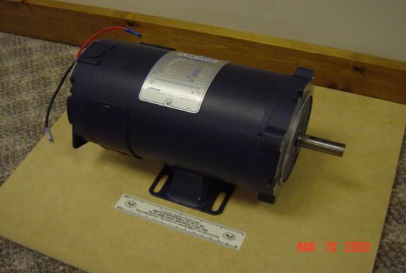
The motor chosen is
a Leeson #108051: ½ horsepower, 1800 rpm permanent magnet motor rated at 24V
and 20 amps continuous rating. This
motor was perfect for EEEAHBMS. And, if
it hadn’t been donated, the motor would have cost $365.00 plus shipping.
The Leeson motor
weighs 23 lbs. and has a 5/8 inch shaft with a hardened metal key. It is approximately 5 ½ inches in diameter,
9 ½ inches long and has a 2 inch long shaft.
The Leeson motor has four mounting holes on the face of the motor as
well as a base that is equipped for mounting.
Figure 4a: Leeson ½ horsepower motor
Later along in the
project an even better British LEM 130 motor was found for EEEAHBMS. However, while its specifications are
better, making it more powerful, much lighter and less bulky, it is more than
twice as expensive as the Leeson 1800, and it would have not been donated.
4.2
Batteries
The EEEAHBMS design
requires a 24 V sealed lead acid battery, rated at 12 amp-hours. After shopping around, it was determined
that there was no way to get batteries inexpensively. And, it was apparent that
the easiest way to achieve the voltage desired was to use two12 V batteries in
series. The most inexpensive batteries
at the desired ratings to be found were at www.Electricscooting.com. So, the two 12 Volt, 12 amp-hour batteries
were ordered for $95.90.
These sealed lead acid batteries weigh 9 lbs each, and are 5 15/16 inches long, 3 3/4 inches tall and 3 7/8 inches wide.
These batteries need a special charger because (see 4.8 Battery Charger) they do not survive overcharging, and they must be charged at a higher voltage than normal wet-cell lead acid batteries. When fully charged with the correct charger, the batteries are actually at 26 V.
Figure 4b: 12 Volt Sealed Lead Acid Batteries
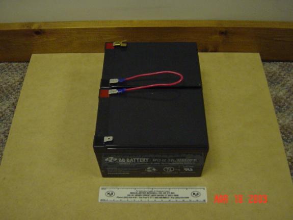
The length of the life of these sealed lead acid batteries
is mainly dependent on how far they are discharged each time. The battery needs to reserve the bottom 20%
of its charge to prolong its life. Without this reserve, a completely drained
battery would give only 100 recharges. By using 80% of the battery capacity the
number of recharges increases to 400-500 cycles. If half of the available
charge is used during each cycle, the battery can survive 700-800 cycles.
Therefore, it is beneficial to avoid fully discharging the battery (information
found at www.currietech.com.au/products/uspd.htm#top).
4.3 Sheave and Bushing
The sheave (pronounced “shĩv”), identified in the EEEAHBMS design, is going to function as the drive wheel for the system. However, before shopping around for a sheave could begin, it was necessary to know the approximate target size for the sheave. This would determine the bicycle’s top speed. According to Connecticut state law, (found at ct.gov) a moped (motor-assisted bicycle) cannot have a top speed of over 30 mph. A moped with a top speed over 30 mph is considered a motorcycle, which requires a special license. Therefore, the top speed could not exceed 30 mph. To be safe, a top speed of 25 mph was selected.
With a top speed of 25 mph selected, and the motor’s top speed of 1800 rpm known, some calculations were made:
Since the circumference of the shiv = 14.67 inches = pD, the diameter of the sheave = 4.6 inches.
Once again, Casey O’Donnell of Motors and Drives came to the rescue. He found two industrial timing belt sheaves which would be perfect for EEEAHBMS’s purposes. One was a little less than 4 inches in diameter and the other was 4.3 inches in diameter. The 4.3 inch sheave was selected, as it would give the bicycle a maximum speed of 23 mph. Once again, Casey was more than generous, donating the sheave as well as the SDSX58 bushing that would adapt it to the 5/8 inch keyed shaft of the Leeson motor.
Figure 4c: Timing
Belt Sheave, Hardened Metal Key, and Bushing
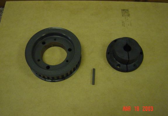
On the left in Figure 4c is the industrial timing belt sheave, with the bushing on the right and the hardened metal key in the middle. The bushing and the hub are connected by 3 hexagonal-head screws that pull the bushing into a slightly tapered hole in the sheave. The taper creates a reliably balanced and secure connection between the bushing and the sheave. In fact, the tapered hole creates such a secure connection that it is nearly impossible to remove the bushing from the sheave once it is in place. In order to remove the bushing, you first remove the screws and then use those screws in three different holes. These holes are designed to do the opposite of the first three: they are meant to help the user push the bushing out of the sheave. With the extra force of the screw action combined with the lever arm of a ratchet wrench, it is possible to remove the bushing from the sheave.
The sheave and the bushing are made of hardened spring steel, making them very difficult to damage. And, because the sheave is a timing belt sheave, it has grooves for the belt it is meant to drive, making it perfect for the EEEAHBMS application. The grooves will provide nice friction between it and the bicycle wheel that it is driving.
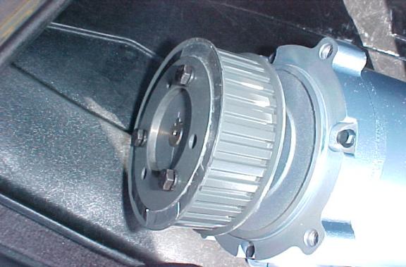
The bushing and sheave mount onto the motor as follows: The hardened metal key is placed into the groove on the shaft of the motor and then the bushing slides over the key and the shaft. The key serves the purpose of creating an irregular, non circular shape for the bushing to connect with, so that the bushing cannot turn. Then a recess-hexagonal drive set screw is tightened down onto the metal key using an Allen wrench, securing the bushing onto the motor. Then, the sheave is connected to the bushing as previously described.
Figure 4d: Sheave and
Bushing Mounted on Motor
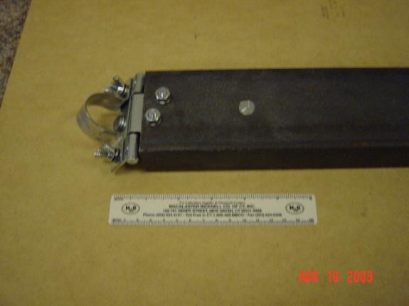
4.4 Channel
The metal channel, as described in the design portion of the project, serves as the “backbone” of the structure of EEEAHBMS. It is mounted to the pole supporting the bicycle seat and to the rear axel of the bicycle. And every other piece of the structure is mounted to it. Therefore, strength is an absolute requirement.
For about $10, two feet of standard industrial 3 inch channel was purchased from Magna Steel in Bridgeport, CT.
Figure 4e: Industrial
3 inch Metal Channel
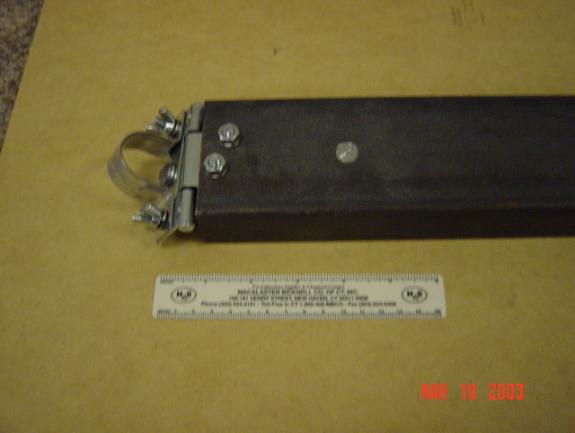
This industrial channel is made of soft steel, which makes
it easy to drill holes for mounting.
And, even though it is very heavy, it is also very strong. The last 7 inches of the channel were
removed later in the project as they were unnecessary and their removal would
save weight. Details about this removal and the T-hinge mounted on the end of
the channel in Figure 4e can be found in section 5 Construction.
4.5 H-Bridge Controller
The EEEAHBMS design requires an H-bridge controller rated at 24V, 20 amps continuous duty. And, as described earlier, a desirable H-bridge would lack bidirectional control and have regenerative braking; dynamic braking was optional.
After a web search of H-bridge suppliers, it was apparent that a commercial unit would cost between $200-$250. After some more searching, an off-brand supplier who sold decent H-bridges for $150 was located. However, this was still above the EEEAHBMS budget. So, the search began for surplus H-bridges.
It turns out that an electric bicycle company that produced the EV Warrior bicycle went bankrupt recently. And, they had thousands of specialty Curtis 1505 commercial unit H-Bridge Controllers in stock when they went bankrupt. So, there are surplus Curtis 1505s on sale for $45 - $60. This was a steal. Curtis controllers are very high quality and would otherwise be priced at or over $150.
Figure 4f: Curtis
1505 H-Bridge Controller
The Curtis 1505 comes with its own mounting case and is unidirectional with regenerative and dynamic braking. The dynamic braking has two triggers. One trigger will enable dynamic braking if it is ever disconnected from the positive terminal of the battery, and the other trigger will enable dynamic braking if it is ever connected to the negative terminal of the battery. This was determined through trial and error experimentation, as limited documentation was available.
The Curtis 1505 also has a built in protection against
discharging the batteries completely. If the batteries ever drop below 18 V, then the controller
will shut down the system automatically.
Such a low voltage is a warning sign that the batteries are nearing
complete discharge.
Finally, the Curtis 1505 has
thermal protection. This consists of a
heat sensor that will shut down the controller if it exceeds a certain
temperature. This is to prevent the
controller from overheating due to high currents.
Figure 4g: H-Bridge Wiring
Figure 4h: H-Bridge Dimensions
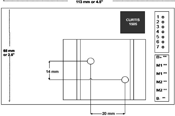
Figure 4g is a wiring diagram of the Curtis 1505, and Figure 4h provides the physical dimensions of the Curtis controller. While Figure 4g also shows that the H-bridge has a built in current sensor, during initial testing, there was no evidence that the current sensor’s reading was accurate. So, it was not used and a different current sensor was devised (see section 6.2 Current Sensor Circuit for more detail).
The control for the Curtis 1505 is intended to be a 5k
potentiometer (see section 4.6 Potentiometer for more details). The 5k potentiometer outputs anywhere from
0V to 4V. If the output is zero volts,
the controller outputs 0V to the motor.
If the output is 4V, the controller outputs 24V. The relationship between the output of the
potentiometer and the output of the controller is linear. And since the relationship between the
output of the controller and the speed of the motor is linear, the relationship
between the output of the potentiometer and the speed of the motor is linear as
well. If any one of the three leads of
the potentiometer disconnects, the controller automatically switches to dynamic
braking.
4.6 5K Potentiometer
A potentiometer is basically a voltage divider. It has three wires connected to a resistor. The first wire is power, connected to one side of the resistor and having a certain given voltage. In the case of the 5k potentiometer, the resistor has a resistance of 5,000 ohms, and the power side of the resistor has a voltage of 4V. The second wire is connected to the other side of the resistor and is ground (0V). Therefore, the resistor has a voltage drop of 4V. The third wire is a wiper, connecting to anywhere between the other two wires, depending on where the knob of the potentiometer is turned. If it is turned all the way towards ground, then the third wire is at ground and carries a voltage of 0V. If it is turned all the way towards power, then it carries the full voltage. And, if the third wire is connected between the power wire and the ground wire, the third wire carries a fraction of the total voltage.
There are two main types of potentiometers: linear taper and logarithmatic taper. The names reflect the relationship between where the third wire is attached and what fraction of the voltage is carried by the third wire. In a linear taper, the relationship is linear. If the third wire is attached half way between, then it carries half of the total voltage. If it is logarithmatic taper, then the ratio is logarithmatic. For the purposes of EEEAHBMS, linear taper is ideal. Logarithmatic would be more complicated than necessary, and is more suited for uses such as audio intensity which are exponential in nature.
Therefore, the potentiometer used for EEEAHBMS is a 5k linear taper potentiometer. Its output is anywhere between 0V and 4V, and, as previously mentioned, the output is linearly related to the speed of the motor. The fact that the power wire of the potentiometer carries only 4V is very convenient. After the bicycle is working, the intention is to have the HandyBoard Computer control the speed of the bicycle, so that the HandyBoard can better protect against current surges. And, since the HandyBoard is capable of outputting up to 9V, having the HandyBoard mimic the potentiometer is trivial.
Figure 4i: 5k Linear
Taper Potentiometer and Knob
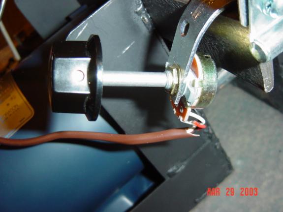
This 5k linear taper potentiometer was purchased at Radio
Shack for approximately $5.
Potentiometers are not expensive.
The knob on the end of the potentiometer was also purchased from Radio
Shack for approximately $2 and attached to the end of the potentiometer to make
the turning of the potentiometer easier.
4.7 HandyBoard (HB) Computer
The HandyBoard is a programmable robotics controller that was designed and built for MIT robotics students. Its programming language is Interactive C, an interpretive subset of ANSI C. Interpretive means that instead of compiling all of the commands into code prior to program execution, the program processes the commands as they come. While this makes Interactive C a little slower than ANSI C, it also makes it much easier to test and debug. But, since Interactive C is only a subset of ANSI C, some functions aren’t available. Even though Interactive C is somewhat limited and not truly a professional programming environment, it is perfectly capable of handling the software requirements of EEEAHBMS.
The HandyBoard and Interactive C provide a “persistent variable” feature. A value stored in a persistent variable will retain its value when the HandyBoard is reset, power cycled, or when the program initializer, main(), exits and is subsequently restarted. A persistent variable will be reset to the initial value when the program is downloaded into the HB. This function will allow the HandyBoard to keep track of information that spans multiple trips, such as distance traveled and energy flow.
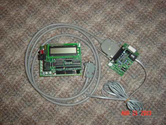
Figure 4j:
HandyBoard, I/O Expansion Board and Computer Interface
The HandyBoard has both analog and digital inputs. An analog input is a voltage while a digital input is an 8-bit binary number. The digital number is unsigned, assumed to be positive, and between 0-255. The HandyBoard also has an A-D converter. It has the capability of reading a voltage, converting it into a digital number, and outputting this digital number. The HandyBoard’s A-D converter reads a voltage between 0V and 5V and outputs this as a digital number between 0-255. There is a linear relationship between this outputted number and the original voltage. The HandyBoard will output 0 if the voltage is 0, 255 if the voltage is 5 and 128 if the voltage is 2.5. The HandyBoard will use this A-D converter to read 2 sensor outputted voltages: one for the current sensor and the other for the odometer (see section 6.2 Current Sensor Circuit and section 6.3 Odometer Sensor Circuit for interfaces).
Figure 4j displays the HandyBoard along with its I/O expansion, which is hidden under the LCD screen. However, the I/O expansion is not necessary for EEEAHBMS. The I/O expansion allows for more inputs as well as giving the HandyBoard an output to control servos. To the right in the picture above is the computer interface and charger for the HandyBoard. This is used to download programs from the computer to the HandyBoard as well as to keep the HandyBoard’s battery charged. The HandyBoard uses a 9.6 V rechargeable nickel-cadmium battery which will be maintained charged in EEEAHBMS
by the larger sealed lead acid batteries.
The HandyBoard has 4 small H-bridge motor outputs that are meant to drive small motors. One of these motor outputs will be connected to a relay which will activate the automatic shutdown. The other motor output will be used to take the place of the 5k potentiometer. The HandyBoard is capable of putting out between -9V and +9V. As previously mentioned, the HandyBoard only needs to output between 0V and 4V to mimic the potentiometer.
Overall, the HandyBoard will function as the onboard computer in EEEAHBMS. Its purpose it to monitor the system and to collect data during use. It will monitor the speed of the motor, the voltage of the battery, the current of the battery, the voltage of the motor, and various other on-off switches (see section 7 Software Design and Implementation for details) The HandyBoard was recycled from a previous robotics project. While it had no impact on the budget of EEEAHBMS, it originally cost $300.
4.8 Battery Charger
As previously mentioned, sealed lead acid batteries need to be charged in a special way. They require charging at a higher voltage than the normal wet-cell lead acid battery, and are very sensitive to being overcharged. For this reason, an available car battery charger was not appropriate for EEEAHBMS.
The battery charger purchased for the purposes of EEEAHBMS was the 24V EV Warrior Charger. It was located on the same website that supplied the surplus H-Bridge controller. This battery charger was also in surplus, and was purchased for $50. A normal battery charger of the same quality would cost $80.
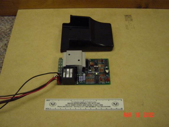
Figure 4k: EV Warrior
Battery Charger
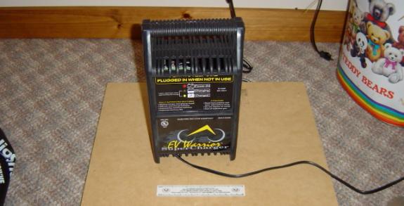
The EV Warrior Charger has special electronics that make it an effective charger for sealed lead acid batteries. The charger monitors the voltage of the batteries, and when the voltage exceeds a certain threshold voltage, the charger shuts down. Then, when the batteries fall below the threshold voltage, the charger turns itself back on again. This protects the batteries from being overcharged as well as maintaining the batteries at full charge.
The EV Warrior Charger is a 5 amp continuous charger. Continuous means that it will provide 5 amps
of current no matter how close to fully charged the battery is. This is much more effective than a normal
battery charger, where the current decays as the battery becomes more and more
charged. The EV Warrior Charger can
charge both batteries from no charge to almost full charge in a little over 2
hours. Because it is rated at 24 volts,
it is capable of charging both batteries at the same time.
4.9 Bicycle Tire and Tube
In the design portion of EEEAHBMS, it was explained that a mountain bicycle tire would not be compatible with a friction drive system. And, since the prototype bicycle for EEEAHBMS is a mountain bicycle, a new rear tire needed to be purchased.
The only tire with a wide, smooth, thick rubber tread that could be found at the approximate size of the old tire was at www.zapworld.com. The old mountain bicycle tire was a 26 X 1.9, which means 26 inches in diameter and 1.9 inches wide. The replacement smooth tire was a 26 X 1.6. It would suit the purposes of EEEAHBMS perfectly. The bicycle tire cost $12.
When the mountain bicycle tire was first replaced with the smooth tire, it was discovered that the tire tube was not compatible to the new tire. Since the smooth tire wasn’t the exact width as the mountain bicycle tire, the tube would not fit. So, a trip was taken to Cycle Fitness in Monroe and the appropriate tire tube was purchased for $5.25.
4.10 Miscellaneous
While the previous sections enumerate all of the major components that were purchased in preparation for the construction of EEEAHBMS, many small components were also purchased during construction. These include nuts, bolts, aluminum angle stock, mounting boxes, wire, connectors, a t-hinge, screws and washers (see section 5 Construction for their use). In addition, many circuitry components were purchased including a circuit board, a photo resistor, an infrared sensor, operational amplifiers, binary circuit counters, resistors and capacitors (see section 6 Electronics for their use). These materials will be enumerated in the context of EEEHBMS construction.
5. Construction
Once the necessary hardware components were collected, construction of the physical
structure of EEEAHBMS began.
5.1 Saddle-Bag
The largest part and highest priority of the construction process was the “saddle-bag.” This piece could not be purchased and needed to be welded from scratch. However, before it could be welded, it needed to be designed. And this required the use of Computer Aided Design (CAD) Software.
So the design phase for the “saddle-bag” was a three step process:
1. Become familiar with CAD
2. Take measurements and draw the saddle-bag
3. Have the saddle-bag welded
A free copy of the CAD Key ’97 R2 program was available. While it is an outdated program and a limited version of CAD, the picture that needed to be drawn was fairly simple and a current professional version costs over $200. Therefore, CAD Key ’97 R2 was used.
The included guided tutorial seemed to be a logical place to become familiar with CAD Key. This tutorial provided exposure to and instructions on how to use the most basic functions of CAD: object creation, transformation, translation, and linking. However, the tutorial was limited and did not provide satisfactory in-depth instruction. So, a series of self-taught lessons were executed in the form of experimentation. In these lessons, a specific tool was focused on and experimented with until understood. The help function of CAD Key proved to be quite useful in these self-taught lessons. It provided a basic explanation of the purpose of the tool, giving the experimentation some direction. Some of the most difficult aspects of CAD to master were:
1. The 3-D construction view
2. Translating objects
3. Re-sizing objects
CAD Key has 9 different construction views, each with a different orientation of the axes. Five of these construction views are in a 2-D plane, while four are in a 3-D plane. It took much practice to be able to predict what an object in one view would look like in the others. An object could look perfectly acceptable in one view and then be totally distorted in another. And, unless the object looks appropriate in all 9 views, it is not correctly drawn.
Translating objects and resizing objects were difficult for similar reasons. When translating or resizing an object in one axis, it is difficult to predict what would happen with relation to the other objects on a screen. A computer monitor is limited in its ability to display 3-D drawings, and therefore a familiarity with the program is necessary in order to predict the results of a translation or resizing.
Once a comfort level with CAD Key was reached, measurements were taken of the bicycle, motor, and battery in order to formulate accurate dimensions for the saddle-bag. It would be very undesirable for the saddle-bag to be welded and then to discover that the motor does not fit correctly, or that that saddle-bag will not mount correctly on the bicycle. So measurements were taken, checked, and double-checked.
Once all of the measurements were procured, it was possible to begin the drawing. However, a problem was encountered along the way. As accurate as the 3-D CAD drawing could be, it was difficult to understand where certain lines were in relation to one another. So, a color coding system was adopted to differentiate between the pieces of the saddle-bag. However, even with the color coding system, it was still difficult to understand in which plane the holes for the sheave and the mounting of the face of the motor were located. So, two drawings were made. The first was the 3-D picture of the saddle-bag, minus the holes. The second was an “unfolded” version of the saddle-bag, labeled with dimensions and including the holes for the motor.
Figure 5a: The
Saddlebag Folded View

Figure 5b: The Saddlebag Unfolded View:
2” 2” 2” 7”

The large hole in Figure 5b is the hole that the sheave slides through while on the motor shaft. This hole allows the sheave to get to the wheel that the two sides of the saddlebag surround. The smaller holes are the holes meant for mounting the saddlebag to the face of the motor.
With the drawings finalized, it was time to find a welder to build the saddlebag. In early January, a presentation about EEEAHBMS was given to the executives of the Business Education Initiative on behalf of the Trumbull High School Science Department. The Business Education Initiative (BEI) is an organization of business men and women interested in supporting the local education system. This interest extends to donating equipment, time and funding for experiments. The THS Science Department decided to present EEEAHBMS as an example of an independent student project in hopes of encouraging further investment into the science department. The result of the presentation was that multiple business executives became interested in providing assistance along the course of the rest of the project.
John Annick, the CEO of BEI, supplied his phone number if and when aid was needed for the project. When the time came to weld the saddle-bag, it was necessary to call for assistance. John Annick supplied contact information for Art Bradshaw from the Aquarion Water Company in Shelton, CT. A meeting was scheduled, and, after a quick review of the drawings, Mr. Bradshaw said that he would fax the drawings over to Richard Cleri, his welder in Stamford.
By the following Monday, Mr. Cleri had welded the saddlebags out of cold-grey steel. However, the drawings weren’t perfectly accurate. Some of the measurements for the distances of the holes from the sides of the sheet metal were “off”, and, as such, Richard Cleri’s holes weren’t all in the correct locations. However, this was not a serious problem because the large, most important hole for the motor sheave was correct. This was the only hole that could not be drilled without a professional as it is 4 1/2 inches in diameter. The error was in the placement of the mounting holes for the face of the motor. which could be corrected using a hand drill at home. (If Figure 5b is examined closely, the measurements of the piece of metal with the holes in it do not add up to the diameters of the holes and the outside areas. This is where the error was.)
When the saddle bag was examined for accuracy in front of Mr. Cleri, he noted that it flexed a lot under its own weight. This did not bode well for mounting a 24 pound motor and two 9 pound batteries. So, Mr. Cleri quickly uncovered some scrap half inch metal pipe, and cut two 3 inch pieces using a band saw. These two pieces of pipe were to be mounted between the two sides of the saddle-bag in order to greatly increase its strength. Without the two pieces of pipe, the top sheet metal could not prevent the flexing.
Each piece of pipe was attached to the faces of the saddle-bag as in Figure 5c using a 5/8 inch lag bolt with a hexagonal head. A nut was used to secure it in place as well as two lock washers.
Figure 5c: The Welded
Saddlebag
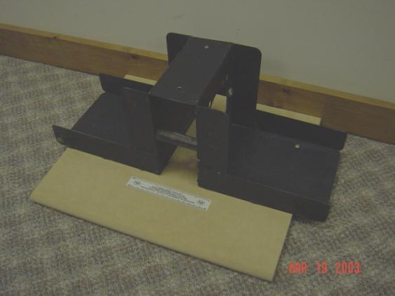
There are two different kinds of lock washers: toothed lock washers and split locked washers. Toothed lock washers are used for the head side of the screw or bolt and prevent the screw from turning. Split lock washers are meant for the nut side of the screw or bolt. They force the nut to be tightened with a lot of torque in order to flatten out the split lock washer. The split lock washer acts like a spring, flattening out as it the nut is tightened. This spring action keeps the nut secure even if it starts to loosen as the split lock washer will just expand to fill in the extra space. Both a toothed lock washer and split lock washer are used on every bolt in EEEAHBMS in order to provide strength.
Once the saddle-bag was strengthened by the addition of the half inch pipe, correctly positioned holes were drilled for the mounting on the motor. After the larger hole was slightly enlarged for the sheave, by using a grinding wheel on a Sears Craftsmen ½ inch drive handheld drill, this aspect of the physical structure was completed.
5.2 T-Hinge and Aluminum
Angle Stock
The next task in the construction portion of EEEAHBMS was to make the channel mountable to the bicycle. There are two mounting points: the seat post and the rear axle of the bicycle.
Figure 5d: Metal
Channel and T-Hinge
The mounting arrangement for the seat post can be seen in Figure 5d. It consists of a T-hinge and piece of 1 inch metal clamp. The T-hinge has three mounting holes, all of which were used in its attachment to the channel. Three ¼ inch holes were drilled in the channel using a small workbench top drill press made in China, model number PTMIN15. Initially, the T-hinge was secured to the channel using a ¾ inch long ¼-20 round head bolt (1/4 inch diameter with 20 threads per inch), nut and lock washers for all three holes. However, later in the construction it was discovered that the rightmost hole in the above picture would block the mounting of the saddle-bag to the channel if a normal bolt and nut were used as planned. Therefore, the screw was changed to a flat head, reversed in its direction (now pointing down) and counter-sunk. Counter-sinking entailed grinding away at the inside of the drilled hole so that the top of the screw would be flush with the channel. With the screw counter-sunk, it would no longer conflict with the mounting of the saddle-bag.
The one inch pipe clamp was chosen because it fit snugly around the seat post of the bicycle. A one inch pipe clamp is meant for pipe with an inner diameter of 1 inch, and an outer diameter of approximately 1 ¼ inches -- an exact match for the seat post. The pipe clamp was secured to the T-hinge using two more ¼-20 bolts, wing nuts, and lock washers. Wing nuts were chosen over hexagonal nuts because they are easier to be undone by hand. And, since these are the nuts that need to be removed in order to mount and un-mount the motor system, it was appropriate to emphasize convenience.
The final addition to the T-hinge was a ¼-20 bolt mounted to the side of the hinge facing the pipe clamp. The head of this screw serves as a shim, ensuring a firm connection between the clamp and hinge and the seat post. This screw head is ground down to give it more of a concave shape in order to make the contact point between it and the screw head smoother.
Figure 5e: Rear
Bicycle Wheel and Aluminum Angle Stock
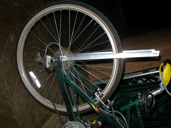
Figure 5e demonstrates how the support members are connected to the rear axle to support the back of the channel. It is constructed of simple aluminum angle stock. After some experimentation with a pile of screws, it was discovered that the threaded mounting holes in the rear axel accept ½ inch 10-32 screws. However, after experimenting on other bicycles, it was also discovered that European bicycles have a metric standard. Therefore, a different set of screws will be needed to mount to the axle of a European bicycle.
With two long pieces of aluminum angle stock mounted to the rear axle, the channel was mountable. Marks were made for the location of the holes on the channel and the appropriate length of the aluminum angle stock. The measurements were made so that the aluminum angle stock would be angled slightly away from the rider for stability. A purely vertical mounting arrangement would not be as strong.
To add flexibility to the mounting arrangement, extra holes were drilled into the channel and into the support members. By using a different set of holes, the height of the channel with respect to the wheel, and the angle at which the aluminum angle stock is mounted can be varied. The aluminum angle stock is connected to the channel by the standard ¾ inch ¼-20 bolts. Standard wing nuts and two lock washers are also used.
Since all bicycles have different sized tires, the distance
from the channel to the rear axle will not be constant. Therefore, in the final design of EEEAHBMS,
the aluminum angle stock support will have to have a variable length. This can be accomplished by two pieces of
aluminum angle stock that slide over one another.
5.3 Motor and Batteries
The next step in the construction process was to secure the motor, batteries and control box to the saddle bag. With the large hole enlarged for the sheave and the mounting holes for the face of the motor corrected, the mounting of the motor required only sliding the motor into place and bolting it to the side saddle. However, since the motor is the most important and heaviest of the components of EEEAHBMS, it was decided that redundancy in the mounting of the motor is appropriate. Therefore, while normally either only the motor face mounting holes or the motor base mounting holes are used, both are used for EEEAHBMS. Two holes were marked and drilled with the drill press for the mounting of the base of the motor and the standard ¼-20 screws, hexagonal nuts, and lock washers are used.
The mounting of the face of the motor wasn’t as simple as assumed. With the holes drilled, the only step left was to screw into the threaded holes. However, the 3/8 inch bolts purchased wouldn’t fit. It was through this experience that it was discovered that there are two types of threads on large bolts: coarse and regular threads. And, the threaded holes on the face of the motor are made for coarse threaded bolts. Therefore, special nuts had to be purchased as well, with standard lock washers being used.
Figure 5f: Motor
mounted on Saddlebag
The mounting of the batteries was not straightforward, since the batteries have no mounting holes. The first thought was to strap the batteries to the saddlebag. However, it was quickly realized that this would be highly unstable and the batteries would most likely slide around. Therefore, a more effective design was necessary.
The battery mounting design involves a tray which would slide in and out of the saddlebag. The batteries would be clamped to the tray, and the tray would be bolted in place to the saddlebag. The tray’s mounting point would be adjustable, giving it freedom to be mounted farther in or farther out, until it effectively balanced the weight of the motor. Fabricating this metal tray would involve the same steps of fabrication as for the saddlebag. However, with the deadline for EEEAHBMS quickly approaching, this complicated battery tray was added to the future improvements list, and a simpler approach was devised.
The problem was that the batteries did not fit snuggly into the saddlebag tray. They had much room to slide around in. So, pink Styrofoam was cut and used as a spacer, making the fit for the batteries tighter. Then, a metal bracket was attached to the back of the saddlebag, securing the motors into place.
Figure 5g: Batteries
Mounted on Saddlebag
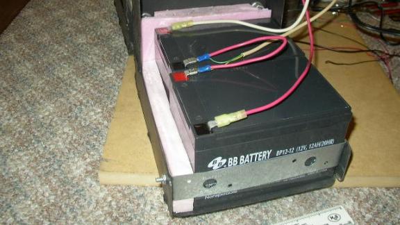
The metal bracket was secured with the standard ¼-20 bolts,
nuts, and lock washers
5.4 Mounting of Saddlebag
Once the batteries and motor were mounted to the saddlebag, it was possible to mount the saddlebag to the channel. The channel was temporarily mounted to the bicycle and then the saddlebag was positioned such that the sheave would be placing an acceptable amount of pressure of the wheel of the bicycle. Two holes were marked and drilled using the drill press. Finally, the saddlebag was secured with the standard ¼-20 bolts, hexagonal nuts, and lock washers.
There is much flexibility in this mounting system. The point at which the channel attaches to the seat post is one point of adjustment. By mounting the channel higher and lower, the sheave puts a varying amount of pressure to the bicycle wheel.
The other point of flexibility stems from the mounting of the saddlebag to the channel. The point at which the saddlebag mounts to the channel is not fixed. It can easily be shifted forwards or backwards, depending on the bicycle to which it is being mounted. Therefore, in the final product, additional holes must be drilled in the channel, to allow room for adjustment in the mounting point of the saddlebag.
5.5 Rear Control Box
It was necessary to mount an electronics control box to the metal channel. An 8x6x3 Project box was purchased from Radio Shack for this purpose and mounted to the channel directly behind the saddlebag.
Figure 5h: Rear
Control Box Mounted on Saddlebag
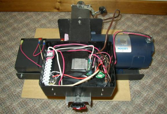
The control box and its respective electronics can be seen
in Figure 5h (see section 6.1.1 Rear Control Box Electronics for more
details). The control box was mounted
to the metal channel using 1/6-32 screws.
Four screws, in pairs of two, were used to mount the control box. Each pair of screws secured a metal bracket
to the mounting box, in order to distribute the force across the plastic
box. This distribution makes it much
more unlikely for the plastic box to crack.
5.6 Front Control Box
Figure 5i: Front Box
Mounting Arrangement
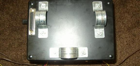
The front control box, housing the HandyBoard, potentiometer, voltage dividers, a relay and a power switch, was mounted to the handlebars of the bicycle. One ¾ inch pipe clamp is attached to each handlebar and a third ¾ inch pipe clamp attaches to the handlebar support. These pipe clamps are mounted to the control box using two 3/16-24 screws each, with square nuts and lock washers. Brackets are used on the inside of the control box for each pair of screws in order to distribute their pressure.
5.7 Trimming the Channel
Once the saddlebag and control box were mounted to the channel, it was obvious that the channel was longer than necessary. And since the channel is very heavy, trimming it would be beneficial to EEEAHBMS. However, trimming metal channel is easier said than done. The tool necessary to do this needed to be found.
The metal channel was brought to the school’s metal shop and
Larry Farrell was very helpful. He
interrupted a Basic Electricity course to trim the metal channel. Using a band saw, which uses its own weight
as the force pressing the saw into the metal, 7 inches of the channel was
chopped off. Using a band saw ensures a
straight and smooth cut.
5.8 Rear Reflector
On most bicycles, the rear reflector is mounted to the seat post. However, with the channel mounting to the seat post, the rear reflector would have to be removed. And, since the rear reflector is a safety requirement for bicycles in most states, this posed a problem.
The solution to this problem was simple. The rear reflector was remounted to the very
edge of the channel as can be seen in the above pictures. Only a hole needed to be drilled. The life of the reflector, however, was short-lived. It was destroyed during the first test run
and will need to be replaced.
6. Electronics
Once the physical structure of EEEAHBMS was constructed, the electronics needed to be designed and implemented. All analog circuits were designed using OrCAD – Demo Version 1999. This is a free downloadable demonstration version of an electronic CAD program. It is used to design and simulate analog circuits. Only the design function was used however. Succeeding in having OrCAD simulate circuits was difficult because it required meticulous attention to the connection of wires and the use of symbols. It is much more practical to draw and label the circuits using OrCAD and test the circuit by actually building it. The process used to learn OrCAD was very similar to the process used to learn CADKey ’97, the main method being experimentation.
All digital logic circuits were designed and simulated using LogicWorks 2001 Version 4.1. This program was loaned by Jeffrey Denenberg, a college professor who uses it for a Digital Logic course at Southern Connecticut University. The process for learning how to use this program included guidance from Jeffrey Denenberg and some self-guided experimentation.
There were three main circuits that needed to be designed
and implemented: a circuit connecting the batteries, controller and motor, a
current sensor circuit, and a odometer circuit.
6.1 Batteries, Controller and
Motor Circuit
There are two halves to the first circuit: the half mounted in the rear control box and the half mounted in the front control box. The two halves are connected via a 25 conductor with male to male DB-25 connectors (see Appendix B Electronics Connections for details). The female ends of the connectors are mounted on the side of each control box. The holes for these female connectors were shaped by first drilling a few holes and then filing away the plastic between these holes with a ¼ inch rotary rasp drill bit. The final cleanup was done with an assortment of files. The odd shape mounting hole was needed because the DB-25 cable has a trapezoidal shape. The female end of the connector also has two screw holes which are mounted by special computer screws and nuts. These screws and nuts were found by salvaging parts from an old broken computer. Lock washers were added to handle vibration. Also, since the front control box is mounted to the bicycle handlebars which turn, the dressing of the DB-25 cable needs to be appropriately handled. The manner by which it is secured to the frame of the bicycle needs to allow slack for the turning of the handlebars, prevent tangling and make sure that the DB-25 does not interfere with the rider.
When the front control box was first mounted, it was realized that a mistake had been made in mounting the female end of the DB-25 connector. It was mounted in the path of the handlebars of the bicycle, making it impossible to connect. For this reason, it had to be shifted farther to the corner of the bicycle, away from the pipe clamps.
Figure 6a: DB-25
Female Connector in the Wrong Spot
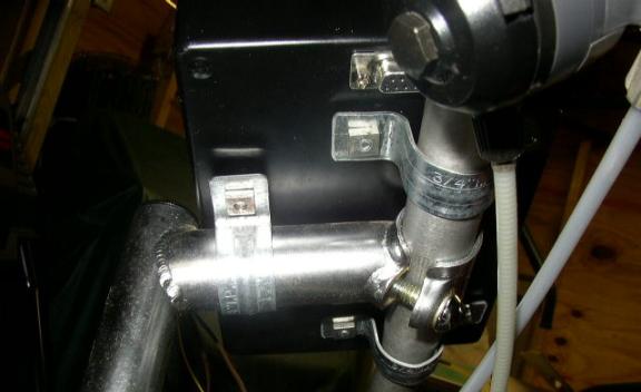
Figure 6b: DB-25
Female Connector Corrected
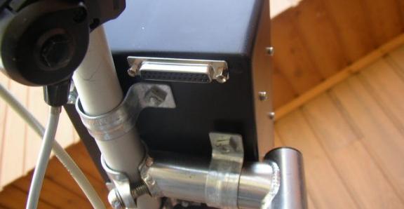
6.1.1 Rear Control Box Electronics
Figure 6c: Main
Circuit for Rear Control Box:
The Curtis H-Bridge controller is mounted in the rear control box using Velcro, making its removal very simple. Referring back to Figure 4g, a diagram of the wiring of the Curtis controller, the motor is connected to the upper M1 pin and the lower M2 pin. The M1 pins are for the positive side of the motor and the M2 pins are for the negative side of the motor. The Curtis H-Bridge is equipped to control two motors. Figure 6c shows the 4 switches that create the H-bridge. Switches U2 and U3 flip together and opposite to switches U4 and U5. When switches U2 and U3 are on, the motor is connected positively across the batteries. When switches U4 and U5 are on, the motor is connected negatively across the batteries.
Again referring back to Figure 4g, the two 12 Volt batteries are connected to the B+ and B- pins. The B+ pin is for the positive end of the battery and the B- pin is for the negative end of the battery.
In parallel with the Curtis controller and the Leeson motor is the XLR charging socket. While the male plug was already attached to the EV Warrior charger, the female socket needed to be ordered separately from the same source for an extra $4.00. The EV Warrior adopted the XLR standard from professional audio low impedance microphone connectors. The female end of the socket is mounted to the bottom of the control box in a ¾ inch hole with two 6-32 countersunk flathead screws. Hexagonal nuts and lock washers are used. This setup provides an easy way to connect the battery charger to the batteries.
Connected in series with the H-bridge controller is a 30 amp continuous duty illuminated power switch. This switch serves as the system’s main on-off switch. At any point, this switch can be toggled, disabling the system. The light provides an indicator as to whether the switch is on or off. However, the light is only rated at 12 Volts and therefore needed to be connected between the two batteries. A diode was added into the circuit to prevent any backwards flow of electricity from the second battery to the light bulb, protecting the light bulb when the power switch is off.
The final piece of this circuit is a type TL 30 amp time delay fuse that is connected in series with the Curtis controller. This time delay fuse is the hardware shutdown for when the current is too high. This fuse will only blow if more than 30 amps are pulled constantly for a period of time. For around 35 amps, that period of time is a minute. For 40 amps, it is 20 seconds. For 60 amps, it is almost instantaneous. This time delay function is compatible with EEEAHBMS because the system can handle up to 80 amps for a minute. Motors, when accelerating, cause the current to surge. This would not be compatible with a fuse that blew instantly when the current spiked. And, even with the time delay, the 30 amp fuse is conservative.
To make the connecting and disconnecting of wires inside the control box easier, a European style barrier strip was added. All power wires entering and leaving the rear control box does so via the barrier strip. The barrier strip can be seen in Figure 5h, mounted on the left side of the control box.
For wires entering the rear control box, holes needed to be drilled into the bottom of the control box for easy access. In order to protect the wires from the sharp edges of the drilled holes, and to make the wires have a snug fit, vinyl grommets were used. These vinyl grommets were purchased from Radio Shack for $2.00.
6.1.2 Front Control Box Electronics
Referring back to Figure 4g, pins 4, 5, and 6 of the Curtis Controller, the pins for the potentiometer, are connected to the front control box via the DB-25 cable. Between the connection of the wiper lead of the potentiometer to the H-Bridge and the lead of the wiper that connects to the variable resistor are two switches: one relay switch and one double-pull double-throw switch. Both of these switches need to be closed or the motor stops. If either switch is off, the desired speed is set to zero.
The relay switch is a switch controlled by the HandyBoard. It is only thrown if the bicycle is moving at a minimum of 3mph. This is a safety measure enumerated in Section 3.5 Safety System to prevent the bicycle from taking off before the rider is ready. The relay is soldered on a printed circuit board which is mounted inside the front control box with 10 mm standoffs. These standoffs use 3-2 X 5mm screws and lock washers to mount to the board and to the box.
The double-pole double-throw switch is the operational on-off switch for the motor. One pole tells the HandyBoard what status the switch is in and the other pole is connected to the motor. The desired speed will only increase above zero if the switch is closed. It is mounted in a ½ inch hole on the side of the front control box.
Figure 6d: Main
Circuit of Front Control Box

The potentiometer is mounted to the side of the front control box, through a 5/16 inch hole. The potentiometer is equipped for mounting with its throat being threaded and having an appropriate hexagonal nut included. And, another 1/8 inch hole was drilled for the peg that prevents the potentiometer itself from turning when the dial is turned. The potentiometer’s voltage is outputted to the Curtis controller which uses the voltage to place a voltage on the motor, and to the HandyBoard which will interpret this voltage and display the desired speed of the bicycle. This setup is temporary until the HandyBoard is capable of controlling the speed directly.
Two miniature voltage divider circuits accompany the relay on the printed circuit board. A voltage divider is two resistors in series with one another, with the first resistor connected to a voltage source and the second resistor connected to ground. The point between the two resistors is a fraction of the voltage applied to the first resistor. This fraction is dependent on the ratio of the first resistor to the sum of the two resistors. The voltage at the point between the two resistors is:
Original Voltage – (First Resistor/(First Resistor + Second Resistor)) X Original Voltage
The voltage dividers are used to reduce the voltage of the batteries and the motor to the range that the HandyBoard can read. The maximum voltage that the batteries can provide is 26 volts, and the maximum voltage that the HandyBoard can read is 5 volts. Therefore, the voltage that the HandyBoard is reading needs to be reduced to 1/6 the voltage of the batteries and the motors.
And, this is exactly what the two voltage dividers do. The first voltage divider allows the HandyBoard to read the motor voltage. It has a 4.7k resistor in series with a 1k resistor, lowering the voltage at the point between the two resistors to approximately 17.5% of the original voltage. The HandyBoard will read this voltage and display the appropriate motor voltage. However, because the motor voltage is constantly switching from positive to negative due to the H-bridge controller, it needs to be averaged out. This is accomplished by placing a capacitor in parallel with the voltage divider. The charging and discharging of the capacitor in response to the flopping of the sign of the voltage serves to average out the voltage of the motor for the HandyBoard.
The capacitor used is a 10,000 nF capacitor (10 X 10-6 Farads). The size of the capacitor was chosen in order to make the reactance (capacitor equivalence of resistance) of the capacitor small compared to the resistor it was across. The smaller the reactance of the capacitor compared to the resistance of the resistor, the smaller the effect the alternating voltage has. The reactance of a capacitor can be calculated as 1/(2p X Frequency X Capacitance). The frequency of the motor voltage is 1 kilohertz, making the reactance of the capacitor approximately 16 ohms, 2/125 that of the 1k resistor.
The second voltage divider allows the HandyBoard to read the battery voltage. Since the battery voltage is not alternating, no capacitor is needed. Therefore, this voltage divider consists of only a 4.7k resistor and a 1k resistor.
Figure 6e: Front
Electronics Box Circuit Board
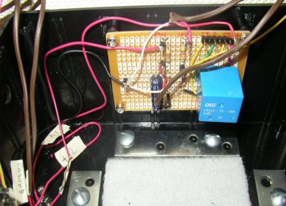
The HandyBoard Computer is mounted in the front control box using Velcro, making its removal very simple.
Figure 6f: Front
Control Box Electronics
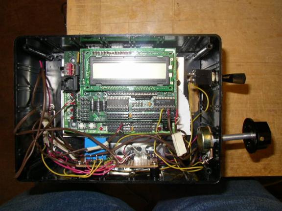
6.2 Current Sensor Circuit
One of the primary jobs of the HandyBoard is to monitor the current of the batteries in order to calculate the power entering and leaving the batteries. However, the HandyBoard is only equipped to read voltage and not current. Therefore, a method needed to be devised in order to make the reading of the current of the battery possible.
The Curtis H-Bridge controller has a current sensor that can be connected to the motor, and initially it was thought that this would be the solution. However, as previously mentioned, after some quick testing, it was determined that the current sensor of the H-Bridge was not reliably accurate.
According to Ohm’s Law, V=IR, voltage is directly proportional to both current and resistance. With a constant and known resistance, either voltage or current can easily be calculated if the other is known. Therefore, with a known resistance connected to the battery, if the voltage difference across the resistor can be read by the HandyBoard, the current of the battery can easily be calculated. This is the method that is used for reading the current of the batteries in EEEAHBMS.
However, this is not as straightforward as it appears. One of the main goals of EEEAHBMS is efficiency. Having a resistor in series with a battery for the purpose of obtaining a current reading is not consistent with this goal: given the high currents that will be produced by the batteries, every ohm of resistance implies a high loss of energy.
Therefore, it was desirable to find the smallest resistor possible.
Figure 6g: Resistance
Table
|
AWG |
Diameter |
Diameter |
Square |
Resistance |
Resistance |
|
|
mm |
inch |
mm2 |
ohm/km |
ohm/1000feet |
|
|
|
|
|
|
|
|
13 |
1,80 |
0,0720 |
2,6 |
6,76 |
|
|
12 |
2,05 |
0.081 |
3,3 |
5.4 |
1.7 |
|
10 |
2.59 |
0.102 |
5.26 |
3.4 |
1.0 |
After a quick internet search, the table in Figure 6g was found at http://ohm.bu.edu/
edf/info/wire-resistance.html. According to this table, 12-gauge wire has 1.7 ohms of resistance for every 1000 feet. A few calculations were made with this data.
1.7 Ω / 1000ft = 1Ω / 588.235 ft = .001 Ω / .588 ft = .001 Ω / 7.05 inches.
Therefore, 7 inches of 12-gauge wire could be used as the equivalent of a 1 milliohm resistor. Such a small resistance is perfect for the purposes of EEEAHBMS.
Yet, using such a small resistor introduces another problem. While the HandyBoard can read any difference of voltage between 0V and 5V, its measurement granularity is not fine enough to read differences across such a small resistor. For example, if the battery is pulling a current of 20 amps, the voltage difference across the milliohm resistor would only be 20 millivolts, a voltage much too small for the HandyBoard to read.
To solve this, an Operational Amplifier, or an OpAmp, which amplifies a voltage difference was employed.
The OpAmp in Figure 6h is a general UA741, the first all-purpose Operational Amplifier to be developed, and the OpAmp used in EEEAHBMS. When the inputted voltage difference is zero, the output is a voltage halfway between Vcc and ground. When a voltage difference is input, this output shifts by this equation:
ΔV of output = -ΔV of input X (R2/R1).
Therefore, the gain of the operational amplifier is equal to the opposite of the ratio of R2 to R1.
The OpAmp also has an internal mechanism to fine-tune its output when the voltage difference of the input is zero, or zero-point. This mechanism is called offset null. If the ends of a potentiometer are connected to pins 1 and 5, and the wiper is connected to ground, the adjustment of the wiper will adjust the zero-point of the Operational Amplifier.
Figure 6h: Basic
Operational Amplifier

For the purposes of EEEAHBMS, the circuit in Figure 6i was designed.
Figure 6i: Current
Sensor Circuit
The HandyBoard can read a voltage from 0V to 5V and this voltage needed to correspond to a current range of approximately 100 amps (-50 amps to +50 amps). Therefore, the middle of the voltage range, 2.5V, needed to correspond with zero amps. So, a 5 volt regulator, powered off of the 24V supply, was used as the upper voltage input for the OpAmp. With the lower input being ground, the zero point of the resistor was 2.5V.
With the range of the OpAmp set at 0V to 5V, the two inputs from the battery when the current was zero to the OpAmp needed to be around 2.5 volts as well. Therefore, a voltage divider was needed to reduce the voltage inputted to the OpAmp from 13V to 2.5V. The voltage divider used was a 4.64k resistor in parallel series with a 1.00k resistor. This reduced the voltage from 13V to 2.3V. While this is not exactly 2.5V, it does not pose a problem. It can be tweaked using the offset null adjustment. And, even if it is not adjusted, it only limits the lower range of the current sensor. And, because the bicycle will only be operating between -20 amps and 20 amps on a regular basis, not being able to read below -45 amps will not be problematic.
The choice of the type of resistors for the voltage divider was very important. The accuracy of the resistors for these voltage dividers was very important in order to achieve the zero current input voltage near 2.5V. There are four types of resistors:
Carbon resistors are made of a cylinder of carbon encased inside plastic. Its resistance rating is determined by the shape of the cylinder of carbon. If the carbon cylinder is long and skinny, the resistor will have a high resistance. If the carbon cylinder is short and fat, it will have a low resistance. These resistors are not terribly accurate.
Metal film resistors are made of an insulated cylinder surrounded by a metal film and encased inside plastic. These resistors are more accurate. The resistance of the resistor is determined by the shape of the resistor and the amount of metal in it. The more metal, and the shorter and thicker the resistor, the lower the resistance.
Wire wound resistors are exactly what they are named: wire wrapped around a insulating cylinder and encased in plastic. While these resistors are accurate, they are normally used to handle high power circuits. The resistance of these resistors is determined by the length and the gauge of the wire used. The longer the wire and the higher the gauge, the higher the resistance.
Thick film resistors are the most accurate. They are made with a piece of ceramic that has a groove in it. This groove is filled with a carbon paste that is fired to harden. Finally, the resistor is milled down under machine control until the desired resistance is reached. These resistors only have 1% error.
Because they are the most accurate, thick film resistors were used for the voltage dividers of the OpAmp circuit.
Finally, the gain of the OpAmp needed to be calculated. With an increase of 2.5 volts corresponding with 50 amps, an increase of one amp should correspond with an increase of .05 volts. Without the OpAmp, the current increase of one amp corresponded with a voltage increase of .000177V (the voltage divider decreased in from .001V). Therefore, the gain needs to be .05V / .000177V = 282. Accordingly, the gain needs to be approximately 300.
In the current sensor circuit, the two resistors that determine the gain are the 270k resistor and the 4.64k resistor. However, the 4.64k resistor is essentially in parallel with the 1k resistor when looking backwards at that piece of the circuit, according to the Thevenin equivalent circuit. A 4.64k resistor in parallel with a 1k resistor is the equivalent of an 823 ohm resistor (1/4.64k + 1/1k = 1/.823k. When calculating resistors in parallel, they add as inverses). Therefore the gain of this OpAmp is 328, approximately what was needed.
In parallel with the 270k resistor is a .47 microFarad capacitor, for the same reason the capacitor was used in the motor voltage divider circuit. The battery current is continually flopping and this capacitor averages out the current.
Finally a 10k-Ohm 15-Turn Linear Taper Cermet Potentiometer
was used as the offset adjustment for the operational amplifier. The potentiometer allows for a very fine
adjustment for the zero-point; it takes a full turn to change the resistance a
mere 667 ohms.
6.3 Odometer Sensor Circuit
Another of the primary purposes of the HandyBoard is to monitor the speed at which the bicycle is traveling and the total distance it has traveled. In other words, the computer needs to know how many times the bicycle wheel has turned. And, since the number of turns of the motor sheave is directly proportional to the number of turns of the bicycle wheel, monitoring the motor sheave was also an option.
There are two general methods for monitoring the rotation of the wheel: an optical sensor and a magnetic sensor. If implemented correctly, both methods work equally well. The optical sensor method was chosen because of HandyBoard accessories described below.
The optical sensor method revolves around Einstein’s Nobel Prize winning photo-electric effect. In this reaction, a photon comes and knocks electrons out of a semi-conductor structure, creating free electrons for current to flow. Therefore, when light (a stream of photons) is shining on the semi-conductor, there is little resistance across it, and when light is not shining on it there is high resistance across it.
Conveniently, one of the HandyBoard’s accessories is an infrared LED and photo-resistor light sensor packaged together in a plastic case. This plastic case has three leads:
The photo-resistor lead gets placed in series with a 47k resistor with a 5V input. Therefore, the point in between the photo-resistor and the 47k resistor is a voltage divider. When the infrared light bounces off the object and comes back to the light sensor, the resistance is very low in the photo-resistor and, therefore, the voltage at the point between the resistors is close to 0V. When the light sensor does not see any of the reflected infrared light, the resistance of the photo-resistor is high and the voltage at the point between the resistors is close to 5V. This cycling between 0V and 5V is a pattern that the HandyBoard can monitor.
The next step was to devise a mechanism to coordinate this cycle with the rotation of the sheave. This was accomplished by covering half of the circumference of the sheave with an aluminum tape and the other half with electrical tape. When the sensor is in line with the aluminum tape, light reflects and the voltage is low. When the sensor is in line with the electrical tape, little light will reflect and the voltage is high. Therefore, a cycling of the voltage corresponds to a rotation of the sheave.
Figure 6j: Motor
Sheave with Light Sensor Tape
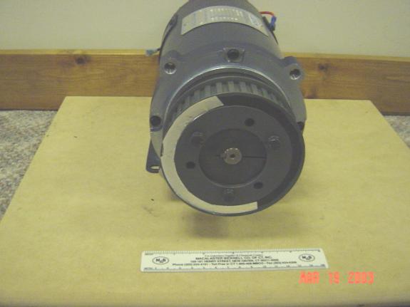
The next step was to mount the LED and light sensor onto the saddlebag and close enough to the sheave so that it would be effective. On the battery side of the saddlebag, a ¾ inch hole needed to be drilled. However, such a large hole is difficult. So, a 3/8 inch hole was drilled and then a chasis-punch drill bit was used to enlarge the hole to ¾ inch. And, finally, a grinder was used to enlarge the hole a little more until it was the correct size.
This mounting hole was used for a ½ inch poly-pipe to threaded pipe adapter. The threaded side of the adapter was used to mount to the saddlebag along with a nut from a Romex electrical connector. The pipe was then cut to the appropriate length so that the end of the pipe is less than a half of an inch away from the sheave. The light sensor and LED are glued to a piece of wood which is glued to the inside of the pipe.
The circuitry for this odometer needed to do two things:
1. First it needed to clean up the output voltage from the light sensor so that is it either 5V or 0V, not almost 5V or almost 0V.
2. Then, it needed to slow the cycling from 5V to 0V down to a speed that the HandyBoard can effectively monitor.
To accomplish the first goal, a comparator was used. A comparator is an OpAmp without the feedback loop, giving it infinite gain. Therefore, the comparator will either output its upper bound voltage or its lower bound voltage, depending on the difference in voltage of the two inputs.
Figure 6k: Optical
Comparator
The upper voltage of this comparator at pin 3 is 5V and the lower voltage of this comparator at pin 12 is ground. Pin 4’s input is the result of a voltage divider which cuts the 5 volts in half down to 2.5V. And, pin 5’s input is from the optical sensor. If light is being reflected, the optical sensor’s output will be close to 0V. And, since this is lower than the 2.5V of the other input, the infinite gain of the Comparator causes its output at pin 2 to be 0V. If light is not being reflected, the optical sensor’s output will be close to 5V. And, since this is above the 2.5V of the other input, the infinite gain of the Comparator causes its output at pin 2 to be 5V. Now, the output from the optical sensor is truly alternating between 0V and 5V.
The second goal of the odometer circuitry was necessary because of the high speeds at which the sheave is rotating. At full load, the motor can rotate the sheave at 1800rpm, or 30 times a second. This would cause 30 full cycles of the voltage, leaving the HandyBoard with 60 changes a second to be monitored. And, the HandyBoard is just not capable of monitoring something that moves this quickly.
So, in order to solve this problem, a 7493 4-bit binary counter chip was employed.
Figure 6l: 7493 4-bit
Binary Counter Chip
Figure 6l shows how a 7493 binary counter chip is employed as a 16 bit frequency divider. If the alternating voltage from the odometer comparator is inputted to CLKA as shown above, Bit A will change voltage once for every complete cycle of the input. Therefore, its frequency is one half that of the input. Since the output of A is connected to the input of B, Bit B will change voltage once for every full cycle of Bit A, making its frequency ¼ the original frequency. Due to internal connections, Bit C will change voltage once for every full cycle of Bit B, making its frequency 1/8 the original frequency. And finally, Bit D will change voltage once for every full cycle of Bit C, making its frequency 1/16 the original frequency. Bit D’s alternating voltage is then outputted to the HandyBoard, at a rate that the HandyBoard can handle. Pins 2 and 3 are reset leads which are grounded to avoid all the bits being set to zero accidentally.
6.4 Printed Circuit Board in
Rear Electronics Box
Figure 6m: Printed Circuit
Board in Rear Electronics Box
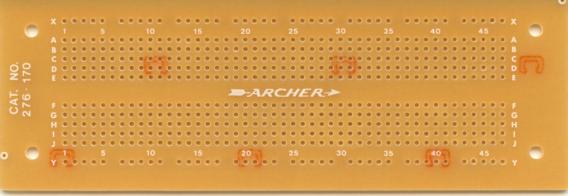
The current sensor circuit and odometer sensor circuit are both soldered onto the same printed circuit board.
Each vertical column of 5 holes in the above circuit board is connected by a copper foil trace on the rear. The top and bottom horizontal rows are each fully interconnected. All wires that attach to the board do so through a 16 pin header (see Appendix B Electronics Connections for details). This header connectorizes the board, making its removal convenient.
Figure 6n: Rear
Control Box Circuit Board
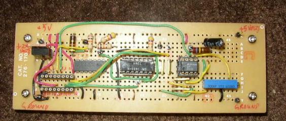
This printed circuit board is mounted to the inside of the rear electronics box the same way that the other printed circuit board was mounted to the front electronics box: it uses four 10 mm standoffs that use 3-2 X 5mm screws and lock washers to mount to the board and to the box.
Figure 6o: Front
Control Box Electronics
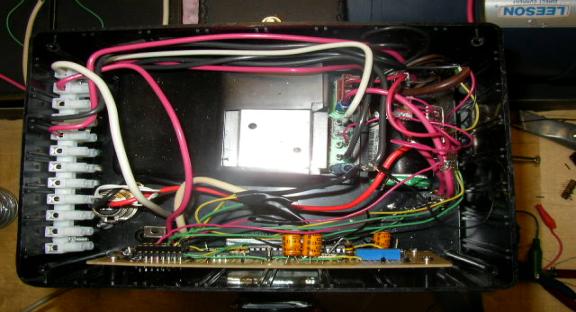
7. Software Design and Implementation
In parallel with the development of the physical structure
and electronics of EEEAHBMS, the HandyBoard software was designed and
implemented.
7.1 Learning Interactive C
Before any programming, or designing, could begin, a comfort level with Interactive C (IC) needed to be obtained. Even though IC 4 is available as freeware, IC 3.2 was used for EEEAHBMS. IC 3.2 is an older commercial version that was already familiar from previous projects.
The majority of the knowledge about programming came from lessons given by Steven Buroff, a professional programmer. Steven Buroff served as the software mentor for EEEAHBMS, providing a solid background in programming and answering questions during the process. Steven Buroff also pointed to online tutorials and documentation on IC which proved to be invaluable during the programming process.
Once some general knowledge of IC had been gained, a few programming experiments needed to be performed for experience before the actually programming process could begin. The first test program was a program testing the display of the HandyBoard. The HandyBoard’s LCD screen contains two rows of 16 characters, with the last character in the second row being a blinking heart to indicate if the program was running. It was not known whether or not that heart would change to a different character if over-printed, so a test needed to be run. The following program was a simple test that printed 32 characters:
char lineOf32Chars[] = "0123456789ABCDEF0123456789ABCDEF";
void
main(){
printf("%s\n", lineOf32Chars);
}
When it was downloaded and run, the LCD screen of the HandyBoard displayed a blinking heart instead of the F. So, it was made clear that the last character in the second row of the LCD screen was not available for displaying.
Another test program was written to test the persistent variable function:
persistent int persInt = 5;
void
main(){
int origValue = persInt;
++persInt;
int finalValue = persInt;
printf("orig=%d, final=%d\n", origValue, finalValue);
}
This program took a number and stored it in the persistent
variable. Then it proceeds to increment
it, and display the original value and the final value for the persistent
variable. When power cycled and run
again, the program retained the new value, demonstrating that the persistent
variable function does indeed work.
7.2 System Requirements
After a little programming experience, Steven Buroff explained that it was time to make a list of system requirements for the software. The following list was generated:
7.3 Software Requirements
Document
Once the System Requirements were enumerated, the next step was to compile a Software Requirements Document. The goal of this document is to enumerate all possible software requirements for initial and future phases of the project. This document should be able to answer all questions regarding software functionality (see Appendix C Software Requirements Document).
The Software Requirements document went through multiple revisions. Each time a draft was completed, Steven Buroff would review it and ask questions that were not answered in the document. Using these questions as comments, the Software Requirements document was edited to be more precise and complete.
Some pieces of the software requirements document were so complicated and difficult to explain, that they required the writing of pseudo-code. Pseudo-code is words in the form of programming that give the general idea of how the piece of the program will be implemented.
The most difficult piece of the software requirements document to explain was the “overload function.” This was the algorithm that the HandyBoard would execute if the current of the system started to get too high. In order to explain it, the following pseudo-code was written:
If(absolutevalue(motorBatteryCurrent) < highWaterCurrentLevel ) {
If(voltageAdjustment > 0) {
voltageAdjustment – voltageAdjustmentParameter = voltageAdjustment
if(voltageAdjustment < 0) {
0 = voltageAdjustment
}
if(motorBatteryCurrent > 0) {
motor(presentControlVoltage – voltageAdjustment);
}
if(motorBatteryCurrent < 0) {
motor(presentControlVoltage + voltageAdjustment);
}
if(voltageAdjustment = 0) {
tell user “overload mode exited”
}
}
If(absolutevalue(motorBatteryCurrent) > highWaterCurrentLevel ) {
Warn user “Current too High, overload adjustment begun”
Warn user *Beeeeep*
absolutevalue(motorBatteryCurrent) – highWaterCurrentLevel = currentDifference;
voltageAdjustment + voltageAdjustmentParameter = voltageAdjustment;
if(currentDifference > highCurrentDifference) {
voltageAdjustment + voltageAdjustmentParameter = voltageAdjustment;
}
if(motorBatteryCurrent > 0) {
motor(presentControlVoltage – voltageAdjustment);
}
if(motorBatteryCurrent < 0) {
motor(presentControlVoltage + voltageAdjustment);
}
}
7.4 Implementing Software
Once the Software Requirements Document was complete, software implementation could begin. Because of time constraints, a high priority list was created to define the functions that were absolutely vital to the EEEAHBMS:
While the Software Requirements Document enumerates functions far beyond this list, these became the Phase I functions. The rest of the functions of the Software Requirements Document were added to the next steps list (see section 10.1 Complete Software), due to the deadline for the project.
The program written has 5 separate files (see Appendix D EEEAHBMS Software). The first file is bike.lis. This file only contains the names of the other four files. When downloaded to the HandyBoard, the HandyBoard automatically downloads the other four files. This is a function of IC 3.2.
The second file, globals.c, initializes all global variable, configurations, constants, and defines all analog and digital ports for the other three files. A global variable means that the variable is available to all files. This is as opposed to a local variable which is only available to the file it is defined in.
The third file, main.c, begins by initializing a few local variables and constants. Main.c then starts three concurrent processes. Two of these processes (watchAnalog() and watchDigital()) are in sensors.c and the third process (watchTime()) is in time.c. Main.c then starts an infinite while loop which sets up local variables, and checks the on-off toggle brake switch on the front box. If the switch is off, it defines the bicycle to be in a stopped true state, setting the desired speed to zero and energizing the relay. If the switch is on, it defines the bicycle to be in a stopped false state, de-energizing the relay and allowing the bicycle to have its desired speed set by the potentiometer. However, since the HandyBoard does not yet have control over the motor, only the energizing and de-energizing of the relay has any effect. The infinite loop also tests whether the motor voltage is above a certain threshold. The threshold corresponds to the motor running at 3mph. If false, the motor is placed in the stopped true state, preventing the motor from running. If true, the motor is placed in the stopped false state. This is the safety measure which prevents the bicycle from moving before the rider is ready. Main.c also uses the information collected from the sensors in sensors.c to calculate the total energy in and out of the battery independently. These numbers are displayed in Watt-hours. And finally, the infinite loop displays the display which corresponds to the current display mode determined by time.c.
The fourth file, sensors.c, is in charge of most of the system’s sensors. Sensors.c defines the process initialized by the pressing of the start and stop button on the HandyBoard. The pressing of the stop button freezes the display mode on the display that it is currently in until the button is released. Once the button is released, the display modes begin to cycle again. The start button, when pressed, resets all persistent variables. Sensors.c also contains the watchAnalog() process which was initialized by main.c. WatchAnalog() is the process that monitors the motor voltage, the battery current and the battery voltage. In addition, sensors.c also contains the watchDigital() process, which was also initialized by main.c. The watchDigital() routine looks for an increase or decrease in the desired speed (not yet in use), the position of the on/off brake switch and does the odometer and speedometer functions. WatchDigital() counts each of the 16 rotations of the sheave and calculates the speed and distance traveled with this data.
The final file, time.c, sets some local variables and resets
the system time to zero. Resetting the
system time to zero every time the program is power-cycled allows the user to
know how much time has elapsed since the system was powered. Time.c then starts an infinite loop which
looks for the press of the stop button.
And, time.c is in charge of the cycling the displays every 5 seconds if
the stop button is not pressed.
8. Testing, Debugging, and Results
As the components of EEEAHBMS were completed, they needed to
be tested and debugged. Then, as a
whole, the system needed to be tested.
And finally, once EEEAHBMS was demonstrably functional, data was
collected and analyzed.
8.1 Initial Testing of Motor,
Controller, and Batteries
Once the motor, controller and the batteries were mounted to the saddlebag and wired together, it was time to test the skeleton of the EEEAHBMS. This would test whether EEEAHBMS could function on its most basic level: as a motorized bicycle and a regenerative braking system. While the physical structure had been completed, and the motor, controller and batteries were wired together according to Figure 6c, most of the bicycle had yet to be completed:
But, at that point in time, the mounting system could be tested, and the basic functionality of EEEAHBMS could be confirmed. The only piece of electronics that needed to be added temporarily was the potentiometer. Since its home, the front control box, was non-existent, it was temporarily wired up and mounted to the back of the channel.
Figure 8a: EEEAHBMS
Ready for Initial Testing
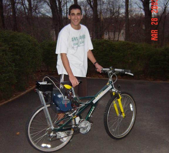

Testing, however, was not as simple as riding the bicycle around the block. There was no guarantee that EEEAHBMS would be safe. Therefore, an alternative methodology was sought.
Conveniently, a teaching professional at the Tennis Club of Trumbull, Danielle Lenois, owns a CycleOps cross training bicycle stand, and was willing to lend it out for short periods of time. The stand is perfect for testing because it lifts the rear wheel off of the ground, allowing it to freewheel. In other words, the rear wheel could be powered without the bicycle moving. After demounting her bicycle, the stand was taken home for the initial testing session.
Mounting of EEEAHBMS onto the bicycle went smoothly. Two structural issues, however, were noted:
1. The pipe clamp that mounts the channel to the seat post of the bicycle has a tendency to slip downwards under the weight of the motor and batteries, even when fully tightened.
2. The entire system was a little unstable left to right. The sheave did not always remain centered around the bicycle wheel.
The first problem was easily solved. A 1 ½ inch stainless steel hose-clamp was tightened to the seat post right below the point that the pipe clamp mounted to the seat post. The hose-clamp was tightened such that it could not slip, and therefore, the pipe clamp could no longer slip.
The other fault, however, was not easily repaired. While solutions were devised (see section 10.2 Stabilizing Physical Structure for details) they required major mechanical work. And, since it did not hinder the functionality of EEEAHBMS, the repair was not a priority and added to Next Steps.
Once the mounting system was debugged, the bicycle was mounted onto the bicycle stand and tested. The results were promising. When the potentiometer was turned, the motor turned on and turned the wheel. The farther the potentiometer turned, the faster the motor turned. When a current meter was placed in series with the battery, a reading of 10 amps corresponded with full speed, well within the systems rating of 20 amps continuous duty. When the potentiometer was quickly turned back down to zero, the meter demonstrated the regenerative braking system slowing down the bicycle with a brief moment of negative current.
The next test was with a rider on the bicycle. The motor was again turned to full speed with the potentiometer, and the meter read 10 amps. When the rider began peddling and “helping” the motor, the meter’s reading began to drop. When the rider peddled as fast as he could, the meter’s current reading went negative, demonstrating that the rider was placing more energy into the system than was needed for that desired speed. And that energy was being funneled back into the motor.
These tests on the bicycle stand demonstrated that EEEAHBMS was functional as both a motorized bicycle and a regenerative braking system.
Once these tests were complete, it was decided that it would be appropriate to test the bicycle off of the bicycle stand. The tester mounted the bicycle, slowly turned up the speed of the potentiometer and then rode around a driveway at approximately 3mph. Everything was running smoothly until the rider decided that it was time to stop.
Figure 8b: First Test
Run of EEEAHBMS off of Bike Stand

Stopping was a problem because the speed control was behind the rider, and the rider was not adept enough to steer the bicycle with one hand. The handbrakes were pressed, but the bicycle reacted to the braking by simply pulling a surge of current. And, since the emergency off switch was yet to be connected, stopping was difficult.
The test run came to an abrupt halt when an effort to reach the potentiometer resulted in steering the bicycle into a bush. In a last ditch effort to stop the bicycle, the rider put his feet down, causing the bicycle to flip.
The rider and EEEAHBMS were very lucky. The rider only suffered some minor cuts and bruises and the only casualty for EEEAHBMS was a smashed rear reflector. The lessons learned from this test include:
Figure 8c: The Ending
of the Initial Test (Reenacted)
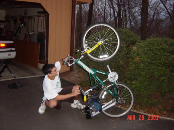
Figure 8d: The
Smashed Rear Reflector
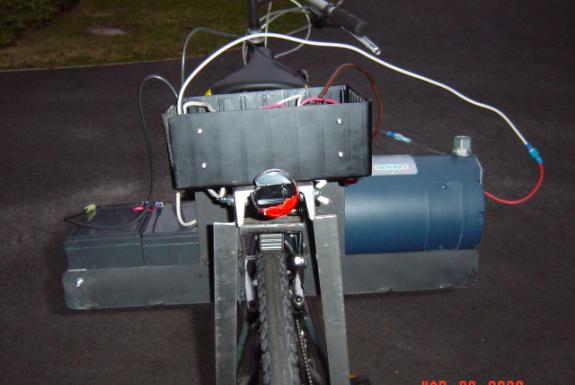
8.2 Testing of the Current
Sensor
After the current sensor was wired according to Figure 6i, it was ready to be tested. The sensor was connected to the 1 milliohm resistor connecting the batteries and then a voltage meter was connected to the current sensor. When the current in the battery is 0, the current sensor should be reading 2.5V. It was reading approximately that, and with some adjustment of the zero point through the offset null function, it read 2.5V.
However, as soon as the potentiometer was turned on and the motor began to move, the voltage reading from the current sensor started to jump around. And, it was moving unpredictably.
At first, it was thought that the current sensor was being asked to amplify too weak of a signal. So, the 7 inches of 12 gauge wire that made the 1 milliohm resistor was replaced with 7 inches of 22 gauge wire. This piece of wire had about 10 times the resistance, and, according to Ohm’s Law (V = IR), would have 10 times the voltage differential across it. With the strength of the signal amplified by 10, the gain of the OpAmp no longer needed to be 300; it needed to be one tenth that, or 30. So, to achieve this new gain, a 33k ohm resistor was placed in parallel with the 270k ohm resistor. The new equivalent resistance was 29.4k ohms. Therefore, the new gain of the OpAmp would be 29.4k ohms / 800 ohms = 36.75. This would be close enough for the purposes of the EEEAHBMS current sensor.
While a stronger signal did help, the current signal was still acting unpredictably. As soon as the potentiometer was turned on, the voltages that the OpAmp outputted were variable.
After hours of unsuccessfully trying to debug the current sensor, the problem suddenly became obvious. When the potentiometer is turned all the way to zero, the H-bridge actually turns off. Therefore, the problem with the current sensor was occurring as the H-bridge turned on -- when the potentiometer was turned up.
It turns out that the H-bridge was creating magnetically induced noise. As soon as the H-bridge is turned on, high currents began flowing in wires near the current sensor, and the magnetic fields created by these wires induced currents and voltages in the current sensor wires. And, since the current sensor is reading such a small voltage, any magnetic noise had a drastic affect on its output.
In order to try to eliminate the effects of the noise, capacitors were added to the circuit (see Figure 8e). The first capacitor to be added to the circuit was 4.7 microfarad capacitor across the 5V power supply. This helped the current sensor slightly. The next capacitor to be added to the circuit was a 1 microfarad capacitor on the input wire to the OpAmp from the batteries. While this also helped slightly, the current sensor was still struggling.
The last two capacitors to be added to the circuit were also 4.7 microfarad capacitors. They were placed across the resistors on the input to the OpAmp. With the addition of these capacitors, the problem with the current sensor had been solved. The debugging of the current sensor was successful, although tedious.
Figure 8e: Modified
Current Sensor Circuit
Once the current sensor was functional, the software had to
be adjusted in order to read the values correctly. This adjustment involved calibrating some constants so that the
HandyBoard correctly interpreted the current sensor.
8.3 Testing of the Odometer
After the odometer was wired according to Figure 6k, it was ready to be tested. The LED and photo-resister were mounted in the tube about a half of an inch away from the sheave and the potentiometer was turned on. As it should, the current sensor was outputting alternating voltages of 0V and 5V every 16 rotations of the sheave. It was functioning correctly and no debugging was necessary.
Once the odometer was proven to function correctly, the
software needed to be calibrated so that it accurately calculated distance
traveled from the alternating voltages.
Once the calibrations were made, the HandyBoard’s displayed distance was
compared to an estimation on how far the motor had traveled using an
approximate rotation speed over a 3 minute interval. When the estimation and the display of the HandyBoard
corresponded within 8%, the functionality of the odometer was proven.
8.4 Software Debugging
For two reasons, the debugging of the EEEAHBMS software was very simple:
1. IC is an interpretive language, not a compiled language. As such, it interprets one command at a time rather than compiling everything at once. This allows the debugging to be done on a command by command basis, rather than trying to debug an entire program at once.
2. The software for EEEAHBMS, in terms of complexity, is relatively straightforward. The majority of errors were syntax errors, and while these are frustrating, they are relatively easy to repair once they are identified.
A good example of a syntax error is an If statement. When making an If statement, you test to see
something is true. For example, IF x =
y, do this. However, this command will
not function to test if x = y. If will
set x = y and therefore, this command is always true. The correct syntax for the If statement is If x == y. The double equals symbol means “test for” in
IC. While the missing equals sign is a
simple error, it will prevent software from functioning.
8.5 Final Testing and Results
Once all of the different components of EEEAHBMS were successfully tested, it was time to test the entire system at once. The CycleOps bike stand was once again borrowed from Danielle, and the bicycle was mounted onto it.
During the mounting procedure, a problem was encountered: the power wires from the control box to the batteries interfered with the wing-nut that secured the aluminum angle stock to the channel. While this was mildly inconvenient, the problem was easily solved by reversing the screw and having the wing-nut on the inside of the channel.
Once EEEAHBMS was mounted entirely, the problem of the system shifting left to right was reevaluated. The shifting problem stemmed from the imbalance in weight of the motor and the batteries. This caused the motor side of the saddlebag to sit lower than the battery side of the saddlebag. The attempted solution to this problem was to have the aluminum angle stock hold the motor side higher than the battery side. However, this solution was not a fine enough adjustment and the use of a different hole on the battery side only worsened the instability from left to right.
It was then realized that a major factor in the system shifting from left to right was the angle of the sheave with respect to the wheel. If the sheave was not perfectly parallel with the wheel, it would push itself out of alignment. And since the angle of the sheave is adjustable through the changing of the position of the pipe clamp that secures the channel to the seat post, the sheave can be made parallel to the wheel. And, when the sheave is parallel to the wheel, the system is not unstable left to right.
Once EEEAHBMS was successfully mounted onto the bicycle, it was time to collect some test data. While the bicycle was on the stand, the energy in and out of the battery was recorded after 60 seconds of the bicycle’s function at different speeds and different exertions of the rider.
Figure 8f: Data
Results From Testing on Bike Stand
|
|
60 seconds without peddling |
60 seconds with medium peddling |
60 seconds with fast peddling |
|
Desired speed = 5mph |
1.2 Watt-hours out 0.0 Watt-hours in |
0.5 Watt-hours out 0.0 Watt-hours in |
0.1 Watt-hours out 0.7 Watt-hours in |
|
Desired speed = 12mph |
2.9 Watt-hours out 0.0 Watt-hours in |
2.4 Watt-hours out 0.0 Watt-hours in |
0.5 Watt-hours out 0.3 Watt-hours in |
|
Desired speed = 24mph |
10.2 Watt-hours out 0.0 Watt-hours in |
8.4 Watt-hours out 0.0 Watt-hours out |
4.8 Watt-hours out 0.0 Watt-hours in |
This data is hard evidence that the regenerative function of the system works. When the motor has to function by itself, energy is consistently leaving the battery. When the rider is aiding the motor with a moderate paced peddling, the motor does not have to use as much energy to maintain speed. And when the rider is sprinting, the motor is acting like a generator, sending the extra energy that the rider is providing back into the batteries. The exception to this is the sprinting test run at 24mph. The rider was not capable of accelerating the bicycle to 24mph, and therefore was only assisting the motor in maintaining the speed. While no energy was sent back to the batteries, the data is consistent.
Peddling against the motor is exhausting for the rider. It takes a lot of energy to have the motor act like a generator and send energy back into the batteries. All of those 60 second test runs had the rider gasping for breath at the end, and the rider is an athlete. From this we can conclude that the majority of the regenerative braking will not stem from the rider. It takes too much effort for the rider to provide energy into the battery while maintaining speed. For this reason, most of the regenerative braking will result from the rider wanting to slow down when traveling downhill. In slowing down, the motor will take that energy and place it back into the batteries the same as it would if the rider was peddling faster than the desired speed.
Analyzing the data more closely, it is evident that the data is consistent with the kinetic energy formula KE = ½mv2. In other words, energy of motion, is proportionate to speed squared. If we look at the data from Figure 8f, the data in the row of desired speed of 24mph is approximately 4 times that of the desired speed of 12mph. According to the kinetic energy formula, every double in speed should result in a quadruple of energy, and it did.
After a successful testing session on the bicycle stand, it was time to test EEEAHBMS on the road, this time with a helmet. The path chosen was a 10% grade hill approximately .15 miles long. Therefore, the distance traveled in a round trip would be .3 miles, with half uphill and half downhill.
The first test run was done without any peddling. The bicycle was set with a desired speed of 12mph and the round trip was made. The energy out of the battery was 7.8 Watt-hours and the energy into the battery was 0.1 Watt-hours (the result of stopping the bicycle at the end of the run). The same trip was repeated, this time with a comfortable peddling pace. The energy out of the battery was 4.4 Watt-hours and the energy into the battery was .2 Watt-hours (again, the result of stopping).
To analyze these numbers, a few calculations need to be done first. The two batteries have a total voltage of 26 V when fully charged and are rated at 12 amp-hours. Since Power = Volts X Amps, and power is measured in Watts, Watt-hours = Volts X Amp-hours. Therefore, the two batteries store a total of 312 Watt-hours.
However, not every Watt-hour will be used for EEEAHBMS efficiently. Only about 2/3 of the battery will be discharged each time, leaving 200 Watt-hours at the disposal of EEEAHBMS. And, accounting for efficiency loss, that number is probably around 170 Watt-hours.
In the first run, a net of 8.7 Watt-hours were exhausted. Therefore, this .3 mile trip can be traveled 170 / 7.7 = 22.08 times before the batteries would be exhausted. Accordingly, the bicycle, without any assistance from the rider can travel 6.623 miles of hilly terrain at 12 mph before needing to be recharged.
In the second run, a net of 4.2 Watt-hours were exhausted. Therefore, this .3 mile trip can be traveled 170 / 4.2 = 40.48 times before the batteries would be exhausted. Accordingly, the bicycle, with assistance that will not exhaust the rider, can travel 12.12 miles of hilly terrain at 12mph before needing to be recharged.
Figure 8g: Testing
EEEAHBMS on the Road
The testing of EEEAHBMS was a complete success. It demonstrated that:
·
The bicycle does function as a motorized bicycle.
·
EEEAHBMS does regenerative braking
·
The data collected by the HandyBoard is accurate
·
The bicycle is safe to ride on the road.
While there are improvements to be
made, EEEAHBMS can be declared functional.
9. Support
EEEAHBMS would have been impossible without the donation of
time and materials from numerous sources.
This section recognizes all the people who helped during the EEEAHBMS
development process.
9.1 Jeffrey Denenberg
Jeffrey Denenberg served as an invaluable resource during
the entire project. As an electrical
engineer, he helped to provide much of the background information necessary to
begin the research for EEEAHBMS.
Experienced in design and implementation, he served as an evaluator of
designs and helped to point out many fatal flaws throughout the design
process. Experienced with the safety
required in the use of dangerous power tools, Jeffrey Denenberg served as a
supervisor during the construction process.
And, as an electrical engineer, Jeffrey Denenberg helped to evaluate the
electronics of EEEAHBMS before they were implemented.
9.2 Steven Buroff
Steven Buroff served as the software advisor of
EEEAHBMS. He shared his experience as a
professional programmer, and taught the design and implementation process that
a successful programmer uses. Steven
Buroff helped to provide a comfort level with IC by giving some programming
instruction. And, finally, he served as
a resource to draw on when any programming questions needed to be answered.
9.3 Motors and Drives
Casey O’Donnell and Motors
and Drives was another invaluable resource. As described in the materials section of this report, Casey
O’Donnell helped to locate the correct motor and sheave for EEEAHBMS and his
company, Motors and Drives, donated
these components. Without this
assistance, the budget for EEEAHBMS would not have been sufficient.
9.4 The Trumbull Business
Education Initiative
After becoming aware of EEEAHBMS through a presentation given on behalf of the Trumbull High Science Department to the Trumbull Business Education Initiative, BEI was incredibly helpful. Their CEO, John Annick provided his telephone number in case any financial or construction assistance was needed. When the request was made for a welder, he supplied contact information for Art Bradshaw of Aquarion in Shelton, CT. Art Bradshaw reviewed the drawings, allowed the use of his digital camera for a few pictures and requested the services of Robert Cleri who welded the saddlebag. Robert Cleri is the machinist that works in the Aquarion substation in Stamford. This assistance was absolutely necessary, and it was given generously and in a timely fashion.
9.5 Larry Farrell
Larry Farrell, a THS technology teacher, provided assistance when the Trumbull High metal shop was needed to trim the metal channel. He interrupted his Basic Electronics course and used the school’s bandsaw to trim the channel.
9.6 The Bass Family and The
Gottlieb Family
The Bass family and the Gottlieb family generously donated the
use of their digital cameras for EEEAHBMS.
The Bass family digital camera is a Sony Cybershot DSCP2 and the
Gottlieb family digital camera is an Olympus DM550. Without the frequent use of these cameras, accurate documentation
of EEEAHBMS would have been impossible.
9.7 Danielle Lenois
Danielle Lenois’ donated of the use of her CycleOps bike
stand, which enabled the safe testing of EEEAHBMS. Without her CycleOps stand, the instrumentation and data
collection of EEEAHBMS would have been more difficult.
10. Next Steps
EEEAHBMS was an ambitious project. As such, logical decisions had to be made as to what could be
feasibly done within the time constraints and what could not. Unlike most projects, however, the
submission of this report does not signal the end of EEEAHBMS. There are still many improvements that can
be made, and work on EEEAHBMS will continue until the implementation is
completed.
10.1 Complete Software
The Software Requirements Document details every possible
function of the EEEAHBMS program.
However, because of time constraints, only the most vital pieces of the
program were implemented. One of the
largest next steps of EEEAHBMS is to complete the software according to the
requirements document (see Appendix C Software Requirements Document).
10.2 Stabilize Physical
Structure
As was discovered during the first test run, the entire structure of EEEAHBMS has the tendency to shift from left to right, de-centering the sheave on the wheel. While this does not affect the functionality of the bicycle, an uncentered sheave does affect the efficiency of the contact between the sheave and the wheel and does increase the probability of slipping.
The first solution devised to solve this problem was to brace the channel to the frame of the bicycle. However, since every bicycle frame is different, this would make EEEAHBMS bicycle specific, which is counter to its goals. So, another, more adaptable solution was devised.
The other solution is to have free-wheeling wheels mounted
to the saddlebag, perpendicular to the motor sheave, rolling on the side of the
wheel. This would prevent the system
from moving left to right and maintain its adaptability, while only adding
minimally to the total friction and energy loss. It does require welding and significant mechanical work, and for
this reason it was added to Next Steps.
10.3 Battery Tray
The mounting of the batteries to the saddlebag can be
greatly improved with an adjustable sliding tray (see section 5.3 Motor and
Batteries). This would allow the
batteries to better counter-balance the motor.
10.4 Lower Resistance and
Higher Current Rating Current Sensor
In the testing and debugging process, the current sensor’s initial resistor was changed from a 1 milliohm resistor to a 10 milliohm resistor in order to improve performance. While this was successful in improving the functionality of the current sensor, that 10 milliohm resistor is a drag on efficiency. At the optimum functioning current of 10 amps, that is a loss of .1V. Therefore, another next step is to look for a better solution to the current sensor problem, taking out that 10 milliohm resistor and replacing it with a smaller one.
After EEEAHBMS was tested on the road, the observation was made that the current sensor wire insulation had melted into the battery. This is a terrible safety hazard. If the wire had melted through the top of the battery as well, the sealed lead acid batteries would no longer be sealed. Therefore, while the current sensor functioned effectively on the test run, it needs to be replaced with a heavier gauge wire in order to not endanger the battery. The current gauge of 22 cannot handle the 20 amp currents that the bicycle pulls when going uphill at 12 miles per hour.
Figure 10a: Melted
Current Resistor
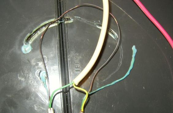
10.5 Further Testing of
EEEAHBMS
While EEEAHBMS was tested and proven functional, there is
still much testing left to do. EEEAHBMS
needs to be tested over longer distances and different terrains to assess its
true functionality as a long distance travel bicycle.
10.6 Belt Friction Drive
During the initial design process, the belt friction drive
was the most desirable drive system design (see section 3.1.1 System
Design). However, the friction drive
system was chosen as the initial drive system design for simplicity. Now that EEEAHBMS is working, steps can be
taken to adapt to the more desirable drive system. And, with this added originality in design, steps can also be
taken to patent EEEAHBMS.
10.7 Lighten Entire Structure
EEEAHBMS is extremely heavy, approximately 67 lbs. One large improvement of EEEAHBMS would be
to find a way to lighten the entire structure without sacrificing
functionality. Lightening would enhance
the system efficiency by making the bicycle easier to accelerate. A simple way to lighten the entire structure
is to find a lighter material for the industrial metal channel. However, the channel does serve as the spine
for EEEAHBMS and supports a lot of weight.
Therefore, care must be taken not to sacrifice too much strength for
weight.
Appendix A Costs for EEEAHBMS
|
Date |
Item |
Quantity |
List Price |
Unit Cost |
Shipping |
Total |
Vendor |
Phone |
Notes |
|
12/10/2002 |
HandyBoard Computer |
1 |
$299.00 |
$0.00 |
$0.00 |
$0.00 |
(636) 536–7179 |
Recycled |
|
|
12/10/2002 |
HandyBoard I/O Expansion board |
1 |
$59.00 |
$0.00 |
$0.00 |
$0.00 |
(636) 536–7179 |
Recycled |
|
|
12/10/2002 |
Interactive "C" 3.2 |
1 |
$35.00 |
$0.00 |
$0.00 |
$0.00 |
(425) 251-9600 |
Recycled |
|
|
12/10/2002 |
Interactive "C" 4.0 |
1 |
$0.00 |
$0.00 |
$0.00 |
$0.00 |
|
Freeware |
|
|
12/10/2002 |
12 volt, 12 amp-hour SLA Battery |
2 |
$43.95 |
$43.95 |
$8.00 |
$95.90 |
(831) 335-1758 |
|
|
|
12/10/2002 |
Curtis PMC 1505 24 volt Controller |
1 |
$150.00 |
$39.95 |
$0.00 |
$39.95 |
(831) 335-1758 |
Surplus |
|
|
12/10/2002 |
Leeson 1800 1/2 HP, 24 volt, 20 amp PM Motor (#18051) |
1 |
$365.00 |
$0.00 |
$0.00 |
$0.00 |
http://www.MotorsAndDrives.com/ |
(203) 877.5828 |
Donated |
|
12/18/2002 |
ZAP Powertire Bicycle Tire 26x1.6 |
1 |
$12.00 |
$12.00 |
$7.00 |
$19.00 |
http://www.zapworld.com/ |
(800) 251-4555 |
|
|
1/20/2003 |
TB Woods SDS58 5/8 inch Bushing |
1 |
$27.00 |
$0.00 |
$0.00 |
$0.00 |
http://www.MotorsAndDrives.com/ |
(203) 877.5828 |
Donated |
|
1/20/2003 |
TB Woods 36L100 36 Tooth 4.3x1 inch Timing Sheave |
1 |
$42.00 |
$0.00 |
$0.00 |
$0.00 |
http://www.MotorsAndDrives.com/ |
(203) 877.5828 |
Donated |
|
1/27/2003 |
5k ohm Potentiometer, Microswitch, Misc. connectors |
|
$8.66 |
$8.66 |
$0.00 |
$8.66 |
Radio Shack - Trumbull, CT |
(203) 459-4250 |
|
|
1/28/2003 |
2 ft X 3 inch Steel Channel |
1 |
$10.00 |
$10.00 |
$0.00 |
$10.00 |
Magna Steel - Bridgeport, CT |
(203) 332-0394 |
|
|
2/3/2003 |
9 volt Relay |
1 |
$4.23 |
$4.23 |
$0.00 |
$4.23 |
Radio Shack - Trumbull, CT |
(203) 459-4250 |
|
|
Date |
Item |
Quantity |
List Price |
Unit Cost |
Shipping |
Total |
Vendor |
Phone |
Notes |
|
2/27/2003 |
30 amp Relay, 9 volt Relay, Power Switch |
1 ea |
$14.49 |
$14.49 |
$0.00 |
$14.49 |
Radio Shack - Trumbull, CT |
(203) 459-4250 |
|
|
3/7/2003 |
ICs: Comparator, 5v Regulator, 2 x 741 OpAmps |
|
$4.52 |
$4.52 |
$0.00 |
$4.52 |
Radio Shack - Trumbull, CT |
(203) 459-4250 |
|
|
3/7/2003 |
Knobs & PC Board |
1 ea |
$5.07 |
$5.07 |
$0.00 |
$5.07 |
Radio Shack - Trumbull, CT |
(203) 459-4250 |
|
|
3/7/2003 |
Capacitor & 2 x Breakaway Headers |
|
$3.52 |
$3.52 |
$0.00 |
$3.52 |
Young Technologies - Derby, CT |
(203) 736-4616 |
|
|
3/15/2003 |
Welded Steel "Side Saddle" Motor &
Battery Holder |
|
$100.00 |
$0.00 |
$0.00 |
$0.00 |
Bridgeport Hydralic Co, Stamford, CT |
(203) 322-9320 |
Donated services and materials via Rotary Club -
built to CAD drawing |
|
3/15/2003 |
Mounting Hardware: T-hinge, Aluminum Angle Stock,
Misc Screws, Nuts, & Washers |
|
$20.65 |
$20.65 |
$0.00 |
$20.65 |
Home Depot - Bridgeport, CT |
(203) 372-7299 |
|
|
3/17/2003 |
Misc. Nuts, Bolts, & Washers |
|
$3.86 |
$3.86 |
$0.00 |
$3.86 |
Henderson-Trumbull Supply - Trumbull, CT |
|
|
|
3/17/2003 |
24 volt SLA Battery Charger and Power Connector |
1 ea |
$57.90 |
$57.90 |
$8.00 |
$65.90 |
(831) 335-1758 |
Surplus |
|
|
3/22/2003 |
Bike Tube - 26x1.6 |
1 |
$5.25 |
$5.25 |
$0.00 |
$5.25 |
Cycle Fitness - Monroe, CT |
(203) 261-8683 |
|
|
3/23/2003 |
8x6x3 Project box |
1 ea |
$7.41 |
$7.41 |
$0.00 |
$7.41 |
Radio Shack - Trumbull, CT |
(203) 459-4250 |
|
|
3/23/2003 |
Fuse, Electrical Connectors, and Misc Screws, Nuts,
& Washers |
|
$11.24 |
$11.24 |
$0.00 |
$11.24 |
Home Depot - Bridgeport, CT |
(203) 372-7299 |
|
|
3/27/2003 |
2 #DB-25 Female Connectors and 6 foot Male-to-Male
Cable |
|
$7.37 |
$7.37 |
$0.00 |
$7.37 |
Radio Shack - Trumbull, CT |
(203) 459-4250 |
|
|
Date |
Item |
Quantity |
List Price |
Unit Cost |
Shipping |
Total |
Vendor |
Phone |
Notes |
|
3/27/2003 |
7x5x3 Project box, Insulated Standoffs (2), Vinyl
Grommets, Small PC Board, and Barrier Strip |
|
$20.50 |
$20.50 |
$0.00 |
$20.50 |
Radio Shack - Trumbull, CT |
(203) 459-4250 |
|
|
3/30/2003 |
Extra 741 Operational Amplifier, IC sockets, Misc
Resistors and VR IC |
|
$8.93 |
$8.93 |
$0.00 |
$8.93 |
Radio Shack - Trumbull, CT |
(203) 459-4250 |
|
|
4/2/2003 |
Velcro, Misc. Hardware |
|
$11.66 |
$11.66 |
$0.00 |
$11.66 |
Home Depot - Bridgeport, CT |
(203) 372-7299 |
|
|
4/3/2003 |
2 Diodes and 4 Capacitors |
|
$7.24 |
$7.24 |
$0.00 |
$7.24 |
Radio Shack - Trumbull, CT |
(203) 459-4250 |
|
|
4/3/2003 |
15-Turn Potentiometer |
|
$2.64 |
$2.64 |
$0.00 |
$2.64 |
Radio Shack - Trumbull, CT |
(203) 459-4250 |
|
|
4/7/2003 |
Totals |
|
$1,348.07 |
|
|
$377.97 |
|
|
|
Appendix B Electronics
Connections
|
Pin |
|
|
|
||
|
DB-25 |
Color |
Header |
Function |
Voltage |
Notes |
|
1 |
Red |
1 |
Switched Battery Voltage |
Plus 18-30v |
Main power to Circuit Board - also to voltage divider |
|
3 |
Red |
NC |
Key Switch |
Plus 18-30v |
Key Switch (24v) to Curtis 1505 |
|
NC |
Green |
2 |
Mid Battery 1 |
Half Battery |
Current sense input - also used to light power switch |
|
15 |
Yellow |
15 |
Mid Battery 2 |
Half Battery |
Current sense input - also used to maintain
HandyBoard battery |
|
16 |
Black |
16 |
Ground |
0v |
|
|
|
|
|
|
|
|
|
NC |
|
NC |
Motor Voltage Raw |
Plus 0-30 |
To filtered voltage divider |
|
|
|
|
|
|
|
|
4 |
Green |
4 |
Current Sensor Output |
Plus 0-5 |
To HandyBoard A/D |
|
NC |
Yellow |
5 |
Optical sensor signal |
5v via 47kW |
Tachometer input (circuit board) |
|
NC |
Red |
6 |
Optical sensor LED power |
5v via 330W |
|
|
7 |
Black |
7 |
Optical sensor ground |
0v |
|
|
14 |
Green |
14 |
Tachometer Output |
5 volt square wave |
From divide by 16 |
|
12 |
Red |
12 |
Logic power |
Plus 5 |
From circuit board regulator |
|
|
|
|
|
|
|
|
8 |
|
NC |
Motor Voltage |
Plus 0-26 |
Secondary Circuit in HandyBoard A/D divides & Filters |
|
|
|
|
|
|
|
|
18 |
Red |
NC |
Potentiometer High |
~4.7 |
Speed control to Curtis 1505 (& HandyBoard A/D
optional) |
|
19 |
Yellow |
NC |
Potentiometer Wiper (via Switch & Relay) |
0.3 – 4.7 |
Speed control to Curtis 1505 & HandyBoard A/D |
|
20 |
Black |
NC |
Potentiometer Low |
~0.3 |
Speed control to Curtis 1505 (& HandyBoard A/D
optional) |
Appendix C Software
Requirements Document
Revision 3
January 22,
2003
Table of Contents
2.5.1 Target Speed Adjustment Switch
2.5.5 Reset Persistent Variables Button
2.5.6 Emergency Shutdown Button
2.8.1 Emergency Shutdown Servo
4.1.8 Reset Persistent Variables Sensor
4.1.9 Emergency Shutdown Sensor
MotorVoltage = (sensorReading – voltageBias) *. 10
MotorCurrent = (sensorReading – currentBias) *. 10
4.2.6 Battery Energy In and Out
4.2.7 Distance Traveled (Odometer)
6.4 Voltage and Current Status View
8.4 Distance Traveled (Odometer)
9.8.4 Hardware Shutdown Detection
10.1 Hardware Configuration Parameters
10.1.2 Increase Target Speed Port
10.1.3 Decrease Target Speed Port
10.1.10 Reset Persistent Variables Port
10.1.12 Motor Speed Control Port
10.2 Software Configuration Parameters
10.2.1 Speed Encoder Ticks Per Rotation
10.2.2 Speed Conversion Factor
10.2.10 Odometer Thread Period
10.2.14 Overload Current Threshold
10.2.15 Overload Adjustment Increment
10.2.16 Overload Current Critical Difference
10.2.17 Battery Voltage Period
10.2.19 Problem Monitor Period
10.2.22 Dead Battery Threshold
10.2.25 Startup Speed Threshold
10.2.26 Shutdown Servo Normal Value
10.2.27 Shutdown Servo Shutdown Value
11.1 Initialize Global Variables
11.2 Perform Battery Recharge Check
11.3 Perform Dead Battery Check
11.7 Perform Startup Speed Check
11.8 Start Battery Energy Thread
11.10 Start Problem Monitor Thread
11.11 Start Motor Control Thread
Figures
Figure 1 - Motor Speed Overload Algorithm
The goal of the hybrid bike project is to build a motorized bicycle that uses regenerative braking to recharge its batteries when the rider is pedaling faster than is necessary to achieve a specified speed.
The software must control or monitor the following hardware.
The bike will be powered by a Leeson 1800 Motor, 24V, ½
horsepower (pulls about 20 amps at rated load), 1800 rpm motor.
The motor controller controls the average voltage applied to the motor. A control voltage is applied to the controller and this controls the actual voltage applied to the motor.
The control voltage is not the same as the motor voltage. The control voltage is a D.C. voltage. The controller applies an A.C. square wave voltage to the motor. Varying the control voltage varies the duty cycle of the square wave, which varies the average D.C. value of the motor voltage.
The software cannot change the motor voltage (or current) directly. The software can only vary the control voltage.
Note: The h-bridge controller will
automatically shut down when the battery voltage drops below 18 volts. This is to protect the lead acid batteries
from full discharge. The software
recognizes that the controller has shut down by noticing that the current is
zero (see section 9.8.4). This
condition is communicated to the user via the display (see section 6.5.4).
The motor will be powered by two 12v, 12amp-hr batteries connected in series to provide a nominal 24V (actually 26 volts at full charge, reduced under heavy current conditions).
The HandyBoard (HB) is a programmable robot controller that can monitor various types of sensors and control motors and servos. The HB also includes an LCD display with 2 rows of 16 characters each (but see section 6). The HB is programmed in Interactive C (IC).
The HB and IC provide a “persistent variable” feature. A value stored in a persistent variable will retain its value when the HB is reset, power cycled, or when main() exits and is subsequently reinvoked. A persistent variable will be reset to the value of its initializer when the program is downloaded into the HB.
2.5.1
Target
Speed Adjustment Switch
A SPDTCO (Single-Pole, Double-Throw, Center-Off) momentary contact switch used to control the bike’s target speed. To the software, this switch appears as two buttons on two separate digital sensor ports. See section 4.1.2 for details.
A simple two-position switch used to set the bike’s performance mode (see section 4.1.6). It is connected to a digital sensor port.
A simple two-position switch used to set the display mode (see section 6)
A button connected to a digital sensor port. When clicked, it causes the display to be advanced to its next view. This is done no matter which mode (frozen or cycling) the display is in. Clicking this button does not change the display’s mode. See section 6.
2.5.5
Reset
Persistent Variables Button
A button used to reset all persistent variables to their default values (see section 4.1.8). It is connected to a digital sensor port.
2.5.6
Emergency
Shutdown Button
A button connected to a digital sensor port and mounted near the bike’s right brake handle. Clicking the button will cause the system to perform an emergency shutdown (see section 4.1.9).
An analog sensor that measures the battery voltage (see section 4.1.3).
An analog sensor that measures the motor’s average voltage (see section 4.1.4).
An analog sensor that measures the motor’s current (see section 4.1.5).
An encoder that measures a value proportional to the number of rotations of the motor. See section 4.2.1 for details.
The encoder increments a counter as it rotates. The count can be read with an IC library function. In order for this to work, the encoder must be connected to one of the digital ports 7, 8, 12, or 13. It should be attached to port 7 or 8 if at all possible since using one of the other ports will cause significant performance degradation.
2.8.1
Emergency
Shutdown Servo
A servo that is used to shut down the bike in an emergency. The servo is connected to the motor controller’s emergency shutdown pin. Rotating the servo will pull the pin and shut down the motor. See section 11.12 for details.
The software will be programmed in IC using the HB library. The software will be divided into three major subsystems, monitor, control, and view.
The monitor subsystem monitors two types of values, direct and computed. Direct values are obtained directly from the hardware. Computed values are computed from the direct values.
An HB encoder measuring the motor speed. The value read from the encoder is the number of ticks since the last time the encoder was reset. The encoder value must be converted to the actual speed (see section 4.2.1).
The target speed is controlled by 2 HB digital sensors (see section 2.5.1), one to increase the target speed and one to decrease it. The magnitude of the increase or decrease per button click is a configuration parameter (see section 10.2.3).
An HB analog sensor with a value in the range 0 – 255. The value read is a linear function of the battery voltage (see section 4.2.3).
An HB analog sensor with a value in the range 0 – 255. The value read is a linear function of the actual average motor voltage; i.e., the D.C. voltage being applied to the motor (see section 4.2.4). This is not the same as the motor control voltage or the battery voltage. This is the value being applied to the motor by the motor controller.
An HB analog sensor. The value read is an integer in the
range 0 – 255 that is a linear function of the actual motor current (which is
the same as the battery current) (see section 4.2.5). The current pulled by the motor controller is
negligible as is the current pulled in maintaining the HB battery.
An HB digital sensor connected to a switch. When the switch is “on” (digital() returns true), then the board is in “high-performance” mode. When the switch is “off”, the board is in “normal” mode. Note that this is a switch, not a button.
An HB digital sensor connected to a button. When the button is clicked, the display is advanced to the next view (see section 6).
4.1.8
Reset
Persistent Variables Sensor
An HB digital sensor connected to a button. When the button is clicked, all persistent variables are reset to their initial values.
4.1.9
Emergency
Shutdown Sensor
A HB digital sensor connected to a button (see section 2.5.6). When the button is clicked, the system performs the hardware shutdown function (see section 11.12), which, in turn, will cause a software shutdown (see section 11.13).
The actual speed of the bike in mph., a linear function of the motor rotation speed encoder (see section 2.7.1). A floating-point value.
The speed is calculated from the encoder reading using the following configuration parameters.
· TICKS_PER_REV (see section 10.2.1)
· SPEED_FACTOR (see section 10.2.2)
· SPEED_PERIOD (see section 10.2.12)
The motor speed global variable (see section 7.1) is updated once every SPEED_PERIOD msecs. The speed is calculated in two steps. First the speed in rpm is computed as:
rpm = ((encoderReading /
TICKS_PER_REV) /
SPEED_PERIOD)
* 1000.0 * 60.0
Next, the speed in mph is computed as follows and stored in the global variable.
mph = rpm * SPEED_FACTOR
All computations in both formulas are carried out in floating-point.
The speed the user has requested in mph. A floating-point value. The target speed is initialized to zero when the system is started. It is then controlled by the target speed switch (see sections 2.5.1 and 4.1.2).
The actual voltage of the battery (in volts), a floating-point value that is always positive. It is a linear function of the battery voltage sensor (see section 4.1.3). The actual battery voltage is obtained by multiplying the sensor reading by a configuration parameter (see section 10.2.4).
The actual average voltage (in volts) being applied to the motor by the motor controller, a floating-point value. It is a linear function of the motor voltage sensor (see section 4.1.4). The motor voltage can be positive or negative depending on whether the motor is consuming power from or supplying power to the battery. Therefore, there are two configuration parameters used to convert the sensor reading to the actual voltage, a bias and a factor. The bias is an integer and the factor is a floating-point value. The formula for computing the motor voltage:
MotorVoltage = (sensorReading –
voltageBias) *
voltageFactor
See sections 10.2.5 and 10.2.6 for descriptions of the configuration parameters.
The actual motor current in amps, a floating-point value (see section 4.1.5). The sensor always yields a positive value but the actual current can be positive or negative depending on whether power is flowing into or out of the motor. Therefore, there are two configuration parameters used to convert the sensor reading to the actual current, a bias and a factor. The bias is an integer and the factor is a floating-point value. The formula for computing the motor current is:
MotorCurrent
= (sensorReading – currentBias) *
currentFactor
See sections 10.2.7 and 10.2.8 for descriptions of the configuration parameters.
4.2.6
Battery
Energy In and Out
We keep track of the total energy consumed by the system
from the battery and supplied by the system to the battery as two separate
floating-point values. When the bike is moving faster than requested, the motor
acts as a generator and supplies power to the battery. When the bike is moving
more slowly than the requested speed, the battery supplies power to the motor.
The units of the energy accumulators are watt-hours. (The battery, at maximum charge, has about 300 watt hours. However, at high discharge rates not all of this energy is available.) The two accumulators (in persistent memory) are initialized to zero. A logical thread runs periodically to sample the instantaneous power and increment one of the accumulators. The period of the thread is in milliseconds (see section 10.2.9). Which accumulator is updated is determined by whether the current is positive or negative. If it is positive, then the motor is consuming energy. If it is negative, then the motor is supplying energy. The instantaneous power is the motor voltage times the motor current.. We are assuming that all power is transferred between the battery and the motor; i.e., the power loss in the controller and any other parts of the system is negligible.
Each time the energy thread runs, it determines which accumulator to update (by checking the sign of the motor current) and then updates it using the following formula.
acc
+= voltage * current * period / (60.0 * 60.0 *
1000.0)
4.2.7
Distance
Traveled (Odometer)
The total distance traveled, in miles, is kept in a floating-point persistent variable. The value is maintained by a thread that periodically samples the bike’s speed (see section 4.2.1), multiples it by the sampling period (see section 10.2.10), and adds it to the odometer. The actual formula is:
acc
+= speed * period / (60.0 * 60.0 * 1000.0)
The control subsystem controls the following values.
The motor speed is controlled by the HB motor() function. The speed is specified as an integer value in the range (-100, 100). A positive speed causes the motor to consume power from the batteries while a negative value causes the motor to act as a generator and supply energy to the batteries.
The motor speed is controlled by a thread (see section 9.7) that runs periodically (see section 10.2.13). The thread determines the correct value for the motor speed and uses the HB motor() function to set that value. The value to set is dependent on the following values.
If the target speed is greater than the current speed, we need to accelerate. If the target speed is less than the current speed, we need to decelerate.
When we are in normal state (i.e., not in overload), the value of the next argument for the motor() function is obtained from one of four arrays of integer values in the range (-100, 100). All four arrays are of the same size. There are two pairs of arrays, one for accelerating and one for decelerating. Each pair of arrays consists of one used for normal performance and one for high performance. Therefore, the combination of accelerate vs. decelerate and the performance mode determines which array to use.
Once the correct array has been determined, the index is calculated as follows.
ndx
= min(floor(abs(targetSpeed – speed)), arrayLength)
The value obtained from the table determines the value to apply to the motor if the system is in safe mode.
If we are in overload, then the value computed above must be modified. After applying the above algorithm to get the “safe mode” value, we use the following algorithm to determine if we are in “overload” mode and, if so, modify the “safe mode” value. The algorithm uses the following values.
The algorithm is given in Figure 1.
Figure
1 - Motor
Speed Overload Algorithm
If the controller is putting out a voltage of zero, the bike is coasting. (slowly decelerating on level ground due to friction losses.) This means that the nominal will never quite be the target speed. If we are going uphill or against the wind, the actual speed will be a little less than the target speed. If going downhill, the actual speed will be a little greater than the target speed. The magnitude of these differences depends on the table entries.
The HB has an LCD display consisting of two rows of 16 characters each. The last character of the second row is used by the system as a “heartbeat” (it flashes if the system is OK) and is thus not available for use by the software. There are thus a total of 31 characters available for output. This is clearly not enough to display all the data we wish to provide the user. Therefore, we display the data in multiple “views”.
The display subsystem operates in one of two modes, “frozen” or “cycling”. In “frozen” mode, a single view is displayed continuously. It is updated at the cycling rate (see section 10.2.18) so that its data is kept current. In “cycling” mode, the subsystem will cycle through the views displaying each for a configured period of time (see section 10.2.18) and then going on to the next.
When the system is running, the display mode (frozen or cycling) is controlled by the “display mode switch” (see section 2.5.3). When the system is shut down (see sections 11.13 and 7.6), the display is always in “frozen” mode and this switch is ignored.
The “advance display” button (see section 2.5.4) will advance the display to the next view irrespective of its current mode (frozen or cycling). It will not affect the mode.
When a fatal condition (such as “dead battery”) occurs, the status view (see section 6.5) is displayed and the display subsystem is frozen so that the error message is constantly displayed.
This view displays the actual speed (see section 4.2.1) and the target speed (see section 4.2.2) as follows.
|
S |
p |
e |
e |
d |
: |
|
D |
D |
. |
D |
|
M |
P |
H |
|
|
T |
a |
r |
g |
e |
t |
: |
D |
D |
. |
D |
|
M |
P |
H |
|
This view displays the energy into and out of the battery (see section 4.2.6) as follows.
|
I |
n |
: |
|
D |
D |
D |
. |
D |
|
W |
- |
H |
|
* |
|
|
O |
u |
t |
: |
D |
D |
D |
. |
D |
|
W |
- |
H |
|
* |
|
The “W-H” stands for “Watt – Hours”. The asterisk will always appear in on row but never both. If current is positive (flowing from the battery to the motor), then the battery is discharging and the asterisk will be in the “Out” row. If the current is negative (flowing from the motor to the battery), then the battery is being charged and the asterisk will be in the “In” row.
This view displays the odometer (see section 8.4) and the battery voltage (see section 8.1) as follows.
|
M |
i |
l |
e |
a |
g |
e |
: |
D |
D |
D |
. |
D |
|
M |
|
|
B |
a |
t |
t |
e |
r |
y |
: |
|
D |
D |
. |
D |
|
V |
|
6.4
Voltage and
Current
Status View
This view displays the status of the battery voltage (see section 4.2.3) and the motor current (see section 4.2.5). When both are in the normal range, the display is as follows:
|
V |
O |
L |
T |
A |
G |
E |
: |
|
O |
K |
|
|
|
|
|
|
C |
U |
R |
R |
E |
N |
T |
: |
|
O |
K |
|
|
|
|
|
If the battery voltage is low, the “OK” is replaced with “LOW”.
If the current is high (in overload), the “OK” is replaced with “HIGH”.
This view is different depending on the system status.
The following view is displayed when the system is running. When this status is displayed, the view is cycled with the other views.
|
P |
E |
R |
F |
: |
|
N |
O |
R |
M |
A |
L |
|
|
|
|
|
|
|
|
|
|
|
|
|
|
|
|
|
|
|
|
|
When the system is in “high-performance” mode (see section 4.1.6), the “NORMAL” is replaced with “HIGH”.
The following view is displayed when the system is in a startup delay waiting for the bike to attain the required speed (see section 11.7). When this status is displayed, the display is frozen.
|
S |
T |
A |
R |
T |
U |
P |
|
D |
E |
L |
A |
Y |
|
|
|
|
D |
D |
. |
D |
|
< |
|
D |
D |
. |
D |
|
M |
P |
H |
|
The following view is displayed when a dead battery condition is detected (see section 9.8.2). When this status is displayed, the display is frozen to the status view; the other views are not displayed.
|
D |
E |
A |
D |
|
B |
A |
T |
T |
E |
R |
Y |
! |
! |
! |
|
|
|
|
|
|
|
|
|
|
|
|
|
|
|
|
|
|
The following view is displayed when a shutdown condition is detected (see section 9.8.4). When this status is displayed, the display is frozen to the status view; the other views are not displayed.
|
S |
H |
U |
T |
D |
O |
W |
N |
! |
! |
! |
|
|
|
|
|
|
|
|
|
|
|
|
|
|
|
|
|
|
|
|
|
|
The following values are kept in non-persistent global variables.
The actual speed of the bike in mph., a floating-point value. See section 4.2.1. This value is maintained by the speed thread (see section 9.6).
The bike speed the user has requested, in mph., a floating-point value. This value is maintained by the target speed monitor (see section 4.2.2).
A flag set when the battery voltage is low. This value is maintained by the problem monitor (see section 9.8.1).
A flag set when the dead battery condition is detected. This value is maintained by the problem monitor (see section 9.8.2).
A flag set when the system is in an overload condition. This value is maintained by the motor controller (see section 5.1).
A flag set when a software shutdown is performed. This flag is set by the shutdown method (see section 11.13). It is cleared during system initialization.
The following values are kept in persistent variables.
The battery voltage, in volts, a floating-point value (see section 4.1.3). This value is maintained by the battery voltage thread (see section 9.1
The total energy supplied to the battery by the system in watt-hours, a floating-point value (see section 4.2.6). This value is maintained by the battery energy thread (see section 9.2).
The total energy supplied to the system by the battery in watt-hours, a floating-point value (see section 4.2.6). ). This value is maintained by the battery energy thread (see section 9.2).
8.4 Distance
Traveled (Odometer)
The total distance traveled, in miles, a floating-point value (see section 4.2.7). This value is maintained by the odometer thread (see section 9.3).
The following logical threads of control are required. They do not necessarily have to be implemented as separate threads or processes. Some of them can be called from a Timer object’s thread.
This thread maintains the value of the “battery voltage” persistent variable (see section 8.1). It gets the voltage from the battery monitor (see section 4.2.3).
The thread that maintains the battery energy accumulators (see sections 4.2.6, 8.2, 8.3, and 10.2.9).
The thread that maintains the value of the odometer global variable (see sections 8.4, 4.2.7, and 10.2.10).
A thread that cycles the display through its views (see sections 6 and 10.2.18).
The HB digital sensor returns a state. In order to detect a button click, the button must be sampled periodically (see section 10.2.11) to detect the button being clicked and then released. This thread must be run fast enough to detect a button click. This single thread handles all of the system’s buttons.
The thread that samples the motor speed and updates the global bike speed variable (see sections 7.1, 4.2.1, and 10.2.12
The thread that controls the motor speed. See sections 5.1 and 10.2.13).
9.8
Problem Monitor
Thread
The purpose of this thread is to monitor the system for various problem conditions. Its period is given by a configuration parameter (see section 10.2.19). The conditions checked for are described in the following sections.
If the battery voltage drops below a threshold (see section 10.2.21), the “low battery voltage” condition is set (see section 7.3). The only action taken when this condition is set is to display it (see section 6.4).
If the low batter condition is set and the voltage is above the threshold, then the condition is cleared.
If the battery voltage is below a configured value (see section 10.2.22), then a global variable (see section 7.4) is set. When this condition is detected, the system performs a hardware shutdown (see section 11.12). This, in turn, will cause a software shutdown (see sections 9.8.4 and 11.13).
.
If the current ever rises above a configured value (see section 10.2.23), we perform a hardware shutdown (see section 11.12). This, in turn, will cause a software shutdown (see sections 9.8.4 and 11.13).
9.8.4
Hardware
Shutdown Detection
If the current ever drops below a configured value (see section 10.2.24), the hardware is assumed to have been shut down, either by the software (see section 11.12) or directly by the user or the hardware itself. In either case, we perform a software shutdown (see section 11.13).
The following sections describe the software configuration parameters.
10.1
Hardware
Configuration Parameters
The HB encoder port number from which to read the motor speed (see sections 4.1.1 and 4.2.1). The HB encoder port number is an integer in the range 0 – 3. It encoder ports correspond to the digital input ports 7, 8, 12, and 13.
10.1.2
Increase
Target Speed Port
The HB digital sensor port number for the “increase target speed” button (see section 4.1.2).
10.1.3
Decrease
Target Speed Port
The HB digital sensor port number for the “decrease target speed” button (see section 4.1.2).
The HB analog sensor port number for the battery voltage (see section 4.2.3).
The HB analog sensor port number for the motor voltage (see section 4.2.4).
The HB analog sensor port number for the motor current (see section 4.2.5).
The HB digital sensor port number for the performance mode switch (see section 4.1.6).
The HB digital sensor port number for the display mode switch (see section 6).
The HB digital sensor port number for the “advance display” button (see sections 2.5.4 and 6).
10.1.10
Reset
Persistent Variables Port
The HB digital sensor port number for the “reset persistent variables” button (see section 4.1.8).
The HB digital sensor port number for the “shutdown application” button (see sections 2.5.6 and 11.12).
10.1.12
Motor Speed
Control Port
The HB motor port number used to control the bike’s speed by controlling the bike motor controller’s control voltage. See section 2.2 and 5.1.
The HB servo port number for the servo that is used to perform a hardware shutdown (see section 11.12). This must be a value in the range 0 – 5.
10.2
Software
Configuration Parameters
10.2.1 Speed Encoder Ticks Per Rotation
An integer value specifying the number of ticks the speed encoder (see section 4.1.1) reads for a single revolution of the motor (section 4.2.1).
10.2.2 Speed Conversion Factor
A floating-point value specifying the factor to multiply the motor’s speed in rpm by to get its speed in mph (see section 4.2.1).
A floating-point value specifying the speed in mph. to add to or subtract from the target speed for each click of the “increase target speed” or “decrease target speed” button (see section 4.1.2).
A floating-point value to multiply the value of the batter voltage sensor by (see section 4.2.3) to get the battery voltage in volts.
An integer value to add to the value of the motor voltage sensor as the first step in converting the sensor reading to a voltage (see section 4.2.4).
A floating-point value to multiply the biased motor voltage value by (see section 10.2.5) to obtain the actual voltage in volts (see section 4.2.4).
An integer value to add to the value of the motor current sensor as the first step in converting the sensor reading to a current (see section 4.2.5).
A floating-point value to multiply the biased motor current value by (see section 10.2.7) to obtain the actual current in amps. (see section 4.2.5).
An integer value specifying the sampling period of the thread that maintains the energy in/out accumulators, in msecs. (see section 4.2.6).
10.2.10
Odometer
Thread Period
An integer value specifying the sampling period of the thread that maintains the odometer, in msecs. (see section 4.2.7).
An integer specifying the period of the button thread in msecs. (see section 9.5).
An integer specifying the period of the speed measurement thread in msecs. (see sections 4.2.1 and 9.6).
An integer specifying the period of the speed control thread in msecs. (see section 9.7).
10.2.14
Overload
Current Threshold
A floating-point value specifying the maximum current that it is safe for the motor/battery circuit to carry, in amps.. When the current exceeds this value, special corrective action is taken by the motor controller (see section 5.1).
10.2.15
Overload
Adjustment Increment
An integer specifying the increment used to modify the motor voltage adjustment term when in “overload correction” mode. This value is used to modify the argument to the motor() function and, as such, has no units (see section 5.1).
10.2.16
Overload
Current Critical Difference
A floating-point value specifying the current that is compared against the difference between the motor current and the “overload current threshold”, in amps. (see section 10.2.14). If the motor current exceeds the “overload current threshold” by more than this value, the “overload motor adjustment increment” (see section 10.2.15) is applied twice in one cycle to correct the condition faster. See section 5.1 for details.
10.2.17
Battery
Voltage Period
An integer specifying the period, in msecs., of the thread that maintains the battery voltage persistent variables (see sections 9.1 and 8.1).
An integer specifying the period during which a single view is displayed in the HB’s display, in secs. (see section 6). Note that this value is in seconds, not milliseconds.
10.2.19
Problem
Monitor Period
An integer specifying the period of the thread that checks for various system problems, in msecs. (see section 9.8).
A floating-point value specifying the battery voltage difference, in volts, used to detect a battery recharge (see section 11.2).
A floating-point voltage specifying the value of the battery voltage, in volts, below which a “low battery” condition is signaled (see section 9.8.1).
10.2.22
Dead
Battery Threshold
A floating-point value specifying the minimum battery voltage for system operation to continue, in volts. If the battery voltage ever drops below this value, a dead-battery condition is signaled (see section 9.8.2).
10.2.23
Safe
Current Limit
A floating-point value specifying the limit, in amps. above which the instantaneous current must not rise. If the current ever rises above this value, the entire system is shut down (see section 9.8.3).
A floating-point value specifying the minimum current expected in a functioning system. If the current ever drops below this value, it is assumed that the hardware has been shutdown and a software shutdown is performed (see section 9.8.4).
10.2.25
Startup
Speed Threshold
A floating-point value specifying the speed, in mph., that must be reached before the bike is started. See section 11.7.
10.2.26
Shutdown
Servo Normal Value
An integer specifying the value to which the shutdown servo (see sections 2.8.1 and 10.1.13) should be set to enable normal system operation. This must be an integer value in the range 0 – 3000.
10.2.27
Shutdown
Servo Shutdown Value
An integer specifying the value to which the shutdown servo (see sections 2.8.1 and 10.1.13) should be set to perform a hardware shutdown (see section 11.12). This must be an integer value in the range 0 – 3000.
The following functions are performed every time the system is started; i.e., every time main() is called. This occurs each time the system is powered up and each time a new program is downloaded into the HB.
11.1
Initialize
Global Variables
Initialize all global (non-persistent) variables.
11.2 Perform Battery Recharge
Check
Compute the value of the battery voltage at system startup (see section 4.2.3) minus the value saved in persistent memory (see section 8.1). If the value exceeds the threshold (see section 10.2.20), indicating that the battery was recharged while the system was powered down, reset all persistent variables.
11.3
Perform
Dead Battery Check
Perform the dead battery check (see section 9.8.2). If the battery is dead, display the appropriate view (see section 6.5.3) and do a software shutdown (see section 11.13)
See section 9.4.
See section 9.5.
See section 9.6.
11.7 Perform Startup Speed Check
Check that the bike’s speed (see section 7.1) is above the startup threshold (see section 10.2.25). Wait at this step until the speed is above the threshold. While waiting here the system should display the “startup delay” view (see section 6.5.2).
11.8
Start
Battery Energy Thread
See section 9.2.
See section 9.3.
11.10
Start
Problem Monitor Thread
See section 9.8.
11.11
Start Motor
Control Thread
Shutdown Functions
The software can shut down the hardware by pulling a pin on the motor controller (see section 2.2). The software does this by rotating a servo (see sections 2.8.1, 10.1.13, 10.2.26, and 10.2.27).
The software is shut down by terminating all of its threads. Normally the status view is displayed to describe the cause of the shutdown and the display frozen (see section 6.5).
When a software shutdown is performed, a global flag is set (see section 7.6). After all threads have been terminated, a few threads are restarted to monitor certain buttons and switches that are supposed to function even when the system is shut down; e.g., the “advance display” button (see sections 2.5.4 and 6).
Note that a shutdown can be performed before startup has been completed. The implementation of shutdown must support this.
Appendix D EEEAHBMS Software
Bike.lis
globals.c
main.c
sensors.c
times.c
Globals.c
/*Constants*/
#define SENSOR_COUNTS_PER_REV 1
#define LOAD_MSG "\n\nInitializing"
#define START_MSG "\n\nIncrease speed to start"
#define ENERGIZE_MSG "\n\nTurn on Motor"
#define INFO_MSG "\n\nMotor atarts at 3 MPH"
#define LOAD_MSG "\n\nInitializing"
#define PEDAL_MSG "\n\nTurn off Motor to pedal"
/*Configs*/
#define INIT_LOOP_SLEEP_TIME 1.0
#define INIT_LOOP_COUNT 5
#define MOTOR_PORT 3
#define RELAY_PORT 1
#define MOTOR_POWER 100
#define RELAY_POWER 100
#define SENSOR_COUNT &lego3_counts /*the variable in which the amount of rotations is stored*/
#define SENSOR_COUNT_RESET 0*SENSOR_COUNTS_PER_REV
#define SENSOR_VELOCITY &lego3_velocity /*the variable in which the velocity of the angle sensor is stored*/
/*Analog Ports*/
#define MOTOR_VOLTAGE_PORT 16 /*Monitors the actual motor voltage*/
#define BATTERY_CURRENT_PORT 18 /*Monitors the battey current*/
#define BATTERY_VOLTAGE_PORT 20 /*Monitors the battey voltage*/
/*Digital Input Ports*/
#define MOTOR_ON_PORT 15 /*Lets the CPU know when the motor is energized*/
#define FASTER_PORT 14 /*Increase desired speed*/
#define SLOWER_PORT 13 /*Decrease desired speed*/
#define DISPLAY_PORT 12 /*Step and hold display mode*/
#define STOP_PORT 11 /*Resets desired speed to zero; Requires 3 MPH to start motor again*/
#define SPEED_SENSOR_PORT 10 /*Monitors the speed sensor*/
/*Global Variables*/
persistent float powerOut = 0.0;
persistent float powerIn = 0.0;
persistent float distance = 0.0;
float speed = 0.0;
int speed_sensor_count = 0;
int analogPID; /*Monitors analog sensors*/
int digitalPID; /*Monitors digital sensors*/
int timePID; /*Monitors timings*/
int stopped = 1; /*System state*/
int faster = 0; /*user input - increase desired speed*/
int slower = 0; /*user input - decrease desired speed*/
int display = 0; /*user input - step and hold display mode*/
int reset = 0; /*user input - reset persistent variables*/
int brake_switch = 0; /*user input - resets desired speed to zero*/
int motor_on = 0; /*Is motor energized?*/
int motor_voltage = 0; /*measurement*/
int battery_voltage = 24; /*measurement*/
int battery_current = 0; /*measurement*/
int rot_speed = 0; /*from rotation sensor, used to calculate speed*/
int rot_count = 0; /*from rotation sensor, used to increment odometer*/
int display_mode = 0; /*used to determine display mode*/
int count = 0;
Main.c
void
main(){
float oldPowerTime = 0.0;
float bv = 0.0;
int bvf = 0;
float bi = 0.0;
int bif =0;
float mv = 0.0;
int mvf = 0;
int pOutf;
float pOut;
int pInf;
float pIn;
float battery_voltage_constant = 28.1/255.0;
float battery_current_constant = 70.0/255.0;
float motor_voltage_constant = 27.0/255.0;
printf("/n/nInitializing");
analogPID = start_process(watchAnalog());
digitalPID = start_process(watchDigital());
timePID = start_process(watchTime());
while(1){
if(reset == 1){
/* Pressing the Handyboard "start" button resets all three persistent variables */
printf("Reset power and odometer");
powerOut = 0.0;
powerIn = 0.0;
distance = 0.0;
sleep(1.0);
}
/* Set up the battery voltage for display */
bv = (float)(battery_voltage)*battery_voltage_constant;
bvf= (int)bv;
bvf= (int)(10.0*( bv-(float)bvf ));
/* Set up the battery current for display */
bi = ( (float)((battery_current)-136) )*battery_current_constant;
bif= (int)bi;
bif= (int)(10.0*( bi-(float)bif ));
if( bif < 0 ) {
bif=-bif; /* Fixes the "tenths" so no extra minus sign */
}
/* Set up the motor voltage for display */
mv = ( (float)(233-motor_voltage) )*motor_voltage_constant;
mvf= (int)mv;
mvf= (int)(10.0*( mv-(float)mvf ));
if(mvf < 0 ) {
mvf =-mvf; /* Fixes the "tenths" so no extra minus sign */
}
pOut= powerOut*0.0166667; /* Display in Watt-Hours */
pOutf= (int)pOut;
pOutf= (int)(10.0*(pOut-(float)pOutf));
pIn= powerIn*0.0166667; /* Display in Watt-Hours */
pInf= (int)pIn;
pInf= (int)(10.0*( pIn-(float)pInf ));
/*Control Motor*/
if(brake_switch == 1){
stopped = 1;
}
if(stopped == 0){
motor(MOTOR_PORT, RELAY_POWER);
motor(1, 0);
}
if(stopped == 1){
motor(1, RELAY_POWER);
motor(MOTOR_PORT, RELAY_POWER);
}
if(motor_voltage < 250){
stopped = 0; /* start the motor if you're already moving */
}
if(battery_voltage < 18){
printf("Battery Low or System is OFF\n");
sleep(1.0);
}
if(display_mode == 0 && battery_voltage >= 18){
printf("BattV=%d.%d DM=0 stopped=%d\n",
(int)bv,bvf,stopped);
}
if(display_mode == 1 && battery_voltage >= 18){
printf("BatCur=%d.%d DM=1 wh=%d.%d-%d.%d\n",(int)bi,bif,(int)pOut,pOutf,(int)pIn,pInf);
}
if(display_mode == 2 && battery_voltage >= 18){
printf("MotorV=%d.%d DM=2 Spd=%d; d=%d\n",
(int)mv,mvf,(int)speed,(int)distance);
}
/* Update the Watt-Minutes every 6 seconds */
if( seconds() - oldPowerTime > 6.0 ){
if(bi>0.0){
powerOut = powerOut + 0.1*bi*bv;
oldPowerTime = seconds();
}
if(bi<0.0){
powerIn = powerIn - 0.1*bi*bv;
oldPowerTime = seconds();
}
}
}
}
Sensors.c
/* This file contains all input sensor functions
The digital input sensors are:
Faster - Increase desired speed (deferred)
Slower - Decrease desired speed (deferred)
Display_Mode - Step and hold display mode
Brake_Switch - resets desired speed to zero and requires 3 MPH to restart
( used On/Off switch for the Brake_Switch function )
Motor_On - Lets the CPU know when the motor is energized
The analog input sensors are:
Rotational_Sensor - provides rotation count and velocity
Motor_Voltage - senses filtered motor voltage
Battery_Voltage - senses battery voltage (18 to 25 volts)
Battery_Current - senses filtered battery current
*/
void
watchAnalog(){
while(1){
motor_voltage = analog(MOTOR_VOLTAGE_PORT);
battery_current = analog(BATTERY_CURRENT_PORT);
battery_voltage = analog(BATTERY_VOLTAGE_PORT);
defer();
}
}
void
watchDigital(){
int old_speed_sensor_state = 0;
int speed_sensor_state = 0;
long old_time = (long)0;
while(1){
faster = digital(FASTER_PORT);
slower = digital(SLOWER_PORT);
display = stop_button();
reset = start_button();
brake_switch = digital(STOP_PORT);
motor_on = digital(MOTOR_ON_PORT);
if(analog(SPEED_SENSOR_PORT) > 127) {
speed_sensor_state = 1;
}
if(analog(SPEED_SENSOR_PORT) < 128) {
speed_sensor_state = 0;
old_speed_sensor_state = 0;
/*count = count + 1; used for testing*/
}
if(speed_sensor_state > old_speed_sensor_state) {
old_speed_sensor_state = speed_sensor_state;
distance = distance + 1.0;
speed = 1000.0/( (float)(mseconds()- old_time) );
old_time = mseconds();
}
defer(); /* give control back to the Operating System */
}
}
Times.c
/*timing indicators are set here*/
void
watchTime(){
float oldDisplayTime = 0.0;
int old_display_mode = 0;
int pressed = 0;
reset_system_time();
while(1){
if(display == 1){
if(pressed == 0){
display_mode = ((display_mode+1) % 3);
old_display_mode = display_mode;
}
oldDisplayTime = seconds();
pressed=1;
}
if(display == 0){
pressed = 0;
if( seconds() - oldDisplayTime > 5.0 ){
display_mode = ((display_mode+1) % 3);
oldDisplayTime = seconds();
old_display_mode = display_mode;
}
}
defer();
}
}