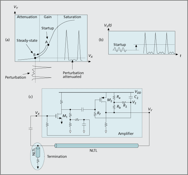
Figure 5. a) Nonlinear transfer curve of the saturating amplifier. In the initial startup, bias point A lies in the gain region. Increased DC component during the transient (Fig. 5b) is used to lower bias of the amplifier, leading to a steady-state bias B; b) DC component of the amplifier output increases as the oscillation grows and forms into a soliton pulse train, c) example oscillator implementation.